
Displacement anti-leakage drainage pipeline mounting system and mounting method thereof

A technology for drainage pipes and installation systems, which is applied in waterway systems, indoor sanitation pipe installations, water supply installations, etc., and can solve problems such as internal leakage, unusability, and unremovable leveling layers, etc., to reduce the height of the filling layer, combine The effect of large area and convenient construction

Pending Publication Date: 2022-06-07
浙江中财管道科技股份有限公司
View PDF1 Cites 0 Cited by
  • Summary
  • Abstract
  • Description
  • Claims
  • Application Information

AI Technical Summary

Problems solved by technology

[0003] In order to solve the leakage of water in the tile layer, the patent CN207176877U "An Anti-leakage Joint of Toilet Drainage Pipe" discloses a leakage water collection device for the tile bonding layer. This product can play a good role in collecting leakage water and is suitable for use It is used when the reserved drainage pipes are not displaced. When renovating old houses, generally only the tile layer and the tile bonding layer are removed. The leveling layer above the floor cannot be removed. At the same time, the bathroom generally needs to be re-arranged and the drainage pipes need to be moved. , in order to reduce the cost and increase the height of the floor space, generally grooves are made on the ground, and the original leveling layer and even the upper part of the floor are cut off to form a groove, and the pipes are arranged in the groove. In this case, the patent CN207176877U cannot be used

Method used


Image

  • Displacement anti-leakage drainage pipeline mounting system and mounting method thereof
  • Displacement anti-leakage drainage pipeline mounting system and mounting method thereof
  • Displacement anti-leakage drainage pipeline mounting system and mounting method thereof

Examples


Embodiment Construction

[0041] The present invention will be further described below in conjunction with the examples. The devices, connection structures and methods involved in the present invention, unless otherwise specified, are all known devices, connection structures and methods in the art.

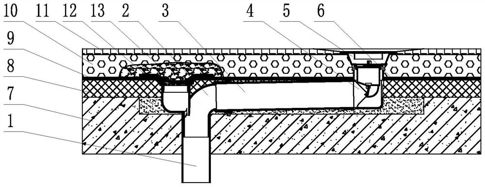
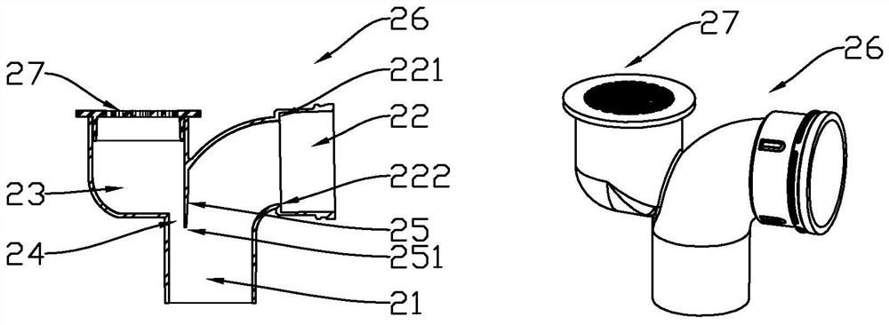
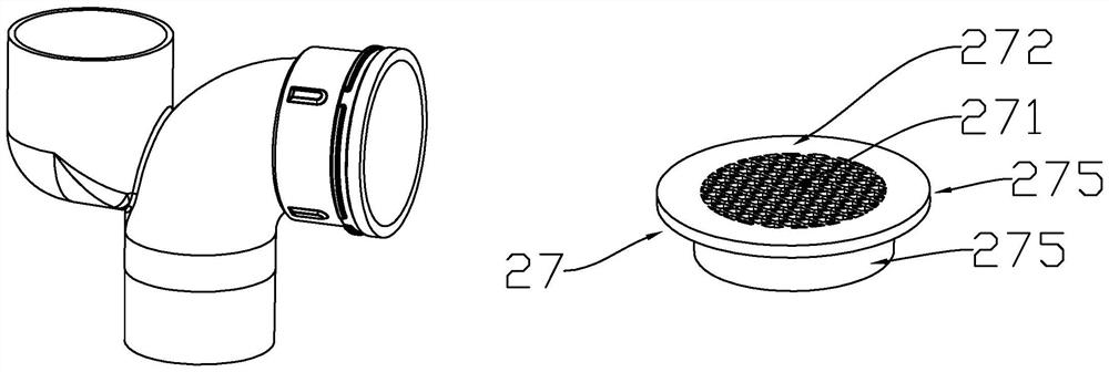
[0042] like figure 1 , as shown, the installation system of the installed displacement anti-leakage drainage pipeline is composed of the floor drain 5 connected to the special elbow 4 for floor drain displacement, the special elbow 4 for floor drain displacement is connected to the displacement pipeline 3, and the displacement pipeline 3 is connected to the displacement prevention elbow Leakage 90º elbow 2, displacement anti-leakage 90º elbow 2 is connected to reserved drainage pipe 1, displacement anti-leakage 90º elbow 2, displacement pipe 3 is placed in the pipe groove 6 opened on the ground 7; Leak-proof 90º elbow including main body 26 and seepage grate 27, see image 3 , the seepage grate 27 includ...


PUM


Abstract

The invention relates to the technical field of indoor drainage parts, and discloses a displacement anti-leakage drainage pipeline mounting system and a mounting method.The displacement anti-leakage drainage pipeline mounting system comprises a floor structure and a displacement anti-leakage drainage pipeline system, and the displacement anti-leakage drainage pipeline system comprises a reserved drainage pipeline, a displacement pipeline and a floor drain; the device further comprises a displacement anti-leakage 90 elbow and a floor drain displacement special elbow, the floor drain displacement special elbow is connected with a displacement pipeline, the displacement pipeline is connected with the displacement anti-leakage 90 elbow, and the displacement anti-leakage 90 elbow is connected with a reserved drainage pipeline. The installation process of all components of the displacement anti-leakage drainage pipeline system is closely related to floor structure construction, leakage water in a ceramic tile layer can be drained, the displacement anti-leakage drainage pipeline system is suitable for displacement installation of drainage pipelines in toilets or balconies, and the hidden danger that sewage in the drainage pipelines flows back into a ceramic tile combining layer through a leakage water collecting opening is avoided; the combination area with the waterproof layer is large, the grooving width is small, and construction is convenient.

Description

technical field [0001] The invention relates to the technical field of indoor drainage parts, in particular to a displacement anti-seepage drainage pipeline installation system and an installation method thereof. Background technique [0002] When the bathroom or balcony is renovated, the drainage pipes reserved for the washbasin generally extend from the floor to the top, and extend through the surface of the tiles to the ground for about 10CM, and then connect the bellows under the washbasin; the reserved drainage pipes for floor drains are generally located between the tiles and the waterproof layer. Intermittent truncation, that is, truncation in the ceramic tile bonding layer, and connection with the drain outlet of the floor drain. After the floor drain is installed, the upper surface is slightly lower than the tile surface. The construction steps are generally, the floor is first leveled with cement mortar, and the waterproof layer is made on it. [0003] In order to...

Claims


Application Information

Patent Timeline
Patent Type & Authority Applications(China)
IPC IPC(8): E03C1/12E03C1/122E03C1/264E04F15/18E03F5/04E03F5/042
CPCE03C1/12E03C1/122E03C1/264E04F15/18E03F5/0407E03F5/042E03F5/0409Y02A30/60
Inventor 刘学敏陆亦飞卢昱文
Owner 浙江中财管道科技股份有限公司
Learn More