An automatic power-off device for charging a new energy electric vehicle

An automatic power-off, electric vehicle technology, applied in the direction of electric vehicle charging technology, electric vehicles, charging stations, etc., can solve the problems of fire, line short circuit, high temperature, and achieve the effect of preventing continuous influence

Active Publication Date: 2022-07-19
品上佳自行车(深圳)有限公司
View PDF6 Cites 0 Cited by
  • Summary
  • Abstract
  • Description
  • Claims
  • Application Information

AI Technical Summary

Problems solved by technology

[0003] In the current charging method, the terminal and the terminal are the most common, but during use, the battery, battery, cable or terminal will heat up, or the temperature will be too high due to other reasons, which will lead to Short circuit, causing fire and other accidents

Method used


Image

  • An automatic power-off device for charging a new energy electric vehicle
  • An automatic power-off device for charging a new energy electric vehicle
  • An automatic power-off device for charging a new energy electric vehicle

Examples


Embodiment 1

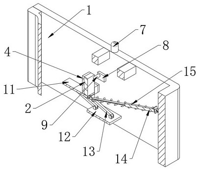
[0035] In one of the more preferred embodiments, the disengagement mechanism includes a carrier plate 11 installed at the bottom of the wiring seat 2, the inner wall of the recessed seat 1 is fixedly mounted with a support plate 12 parallel to the carrier plate 11, and the top of the support plate 12 is connected to the bearing plate 11. A plurality of connecting rods 13 are hinged between the bottom of the plate 11, and a telescopic rod 14 is hinged between the outer wall of the bearing plate 11 away from the terminal 3 and the inner wall of the indented seat 1, and spring seats are installed at both ends of the telescopic rod 14. A tension spring 15 is fixedly installed between the two spring bases. In the state of contact and energization, the thermal trigger assembly limits the terminal base 2 and makes the tension spring 15 in a deformed and stretched state.

[0036] like Figure 5 As shown in the figure, a parallelogram structure is formed between the bearing plate 11 , ...

Embodiment 2

[0048] In another preferred embodiment, the disengagement mechanism is installed on the rotating shafts 18 on the outer walls of both sides of the terminal block 2. The rotating shafts 18 are all rotatably connected to the inner wall of the indented base 1, and the rotation of the torsion spring 19 can make the terminal 3 separate from the terminal block. , the outer wall of one of the rotating shafts 18 is sleeved with a torsion spring 19, and the two ends of the torsion spring 19 are respectively fixedly connected with the inner wall of the indented seat 1 and the outer wall of the wiring seat 2. In the state of contacting with electricity, the thermal trigger assembly will connect the wiring The seat 2 limits the position and causes the torsion spring 19 to twist and accumulate deformation potential energy.

[0049] like Figure 8 and Figure 9 As shown in the figure, by rotating the terminal block 2, the torsion spring 19 will be twisted to accumulate the deformation pote...


PUM


Abstract

The invention discloses an automatic power-off device for charging a new energy electric vehicle. The outer wall is also provided with a heat-conducting plate in contact with the terminal, an insulating sheath is arranged inside the stubby seat, a breakthrough gap is formed on the insulating sheath, and the insulating sheath is located at a part of the terminal away from the terminal. On the side, the connecting post has two states of contacting and being insulated and inserted into the sleeve. The inner wall of the indented seat is provided with a disengagement mechanism for limiting and locking the connecting seat. In the contacting state, the disengaging mechanism makes the connection The post keeps working statically, and the disengagement mechanism includes a thermal trigger assembly. In the present invention, when overheating occurs during the charging process, the terminal post will be rapidly disengaged from the connection with the terminal and enter into the insulating sheath at the same time, forming an anti-shortage pick up protection.

Description

technical field [0001] The invention relates to the technical field of electric vehicle charging equipment, in particular to an automatic power-off device for charging new energy electric vehicles. Background technique [0002] Whether it is a new energy electric vehicle or a fuel engine vehicle, the vehicle needs electricity when it is started. The ignition system of the vehicle contains an on-board battery for starting. During use, the battery is usually depleted due to various unexpected factors. [0003] In the current charging method, terminals and terminals are the most common, but during use, the battery, battery, cable or terminal will heat up, or the temperature will be too high due to other reasons, which will lead to Short circuit of the line, causing fire and other accidents. SUMMARY OF THE INVENTION [0004] The purpose of the present invention is to provide an automatic power-off device for charging a new energy electric vehicle, which is capable of rapidly ...

Claims


Application Information

Patent Timeline
Patent Type & Authority Patents(China)
IPC IPC(8): H01R13/60H01R13/40H01R13/713H01R13/502B60L53/16
CPCH01R13/60H01R13/40H01R13/7137H01R13/502B60L53/16H01R2201/26Y02T90/14
Inventor 沈胜阳高永军
Owner 品上佳自行车(深圳)有限公司
Why Eureka
Try Eureka