
Loop filter of phase shift keying demodulation circuits and phase shift keying demodulation circuit

A technology of loop filter and demodulation circuit, which is applied in the field of signal processing, can solve the problem that the loop filter circuit cannot correctly estimate the input of the filter, the performance of the loop filter circuit is very poor, and the loop filter circuit cannot correctly estimate the input Situation and other issues

Active Publication Date: 2014-12-10
SHANGHAI EASTSOFT MICROELECTRONICS
View PDF2 Cites 0 Cited by
  • Summary
  • Abstract
  • Description
  • Claims
  • Application Information

AI Technical Summary

Problems solved by technology

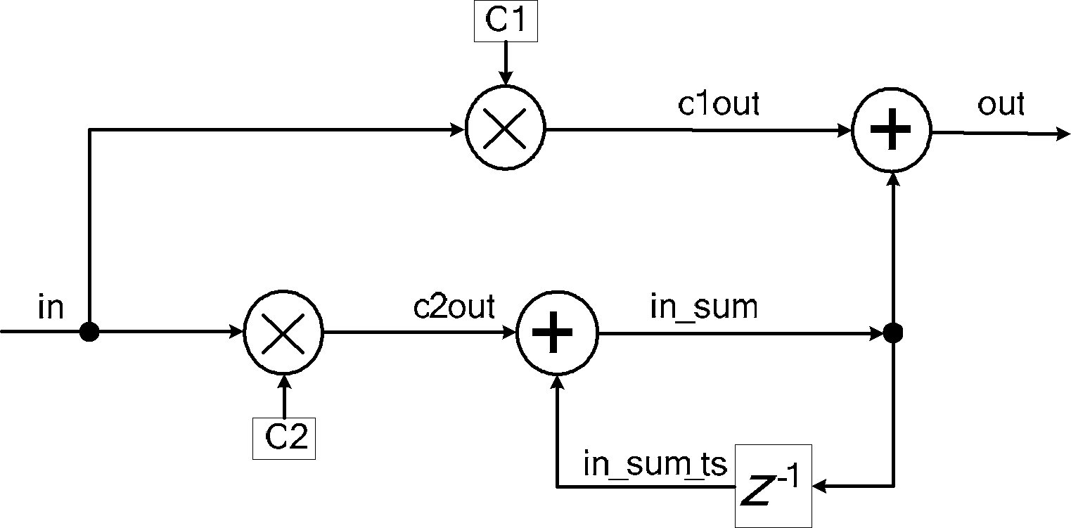
[0005] In the following two cases, the loop filter circuit will not be able to correctly estimate the input situation. First, when the input of the loop filter input is a large noise interference, that is, in is large, the output c2out of the second multiplier is relatively large. Large, the addition of the output in_sum_ts and c2out of the unit delay device results in a larger output in_sum, and a larger in_sum will result in a larger in_sum_ts. Even if the output c2out of the second multiplier becomes smaller, the sum of c2out and in_sum_ts and in_sum is still large , which eventually leads to the loop filter output out obtained by adding c1out and in_sum in the first adder is always large; the second is that the initial value of the output in_sum of the unit delay in the loop filter is 0, and in_sum will be in the actual operation. 0, and c2out is added to the output in_sum_ts of the unit delay to obtain in_sum, and at the same time in_sum passes through the unit delay Z-1 to obtain the signal in_sum_ts. There is a small input biased in a certain direction within a period of time, causing the loop filter input in to bias in a certain direction for a period of time. After the accumulation of the above integration circuit, it will eventually cause in_sum to accumulate a large amount biased in a certain direction. When the actual When the signal comes, because the value of in_sum is large, in_sum_ts will be large, and the sum of c2out and in_sum_ts and in_sum will be large, which will eventually lead to a large loop filter output out
[0006] In the above two cases, the loop filter circuit cannot correctly estimate the input condition of the filter, so that the performance of the loop filter circuit is very poor, so that the demodulation system cannot effectively and quickly track the phase of the upper carrier, resulting in poor demodulation performance

Method used


Image

  • Loop filter of phase shift keying demodulation circuits and phase shift keying demodulation circuit
  • Loop filter of phase shift keying demodulation circuits and phase shift keying demodulation circuit
  • Loop filter of phase shift keying demodulation circuits and phase shift keying demodulation circuit

Examples


Embodiment Construction

[0020] In order to make the purpose, technical solutions and advantages of the embodiments of the present invention clearer, the technical solutions in the embodiments of the present invention will be clearly and completely described below in conjunction with the drawings in the embodiments of the present invention. Obviously, the described embodiments It is a part of embodiments of the present invention, but not all embodiments. Based on the embodiments of the present invention, all other embodiments obtained by persons of ordinary skill in the art without creative efforts fall within the protection scope of the present invention.

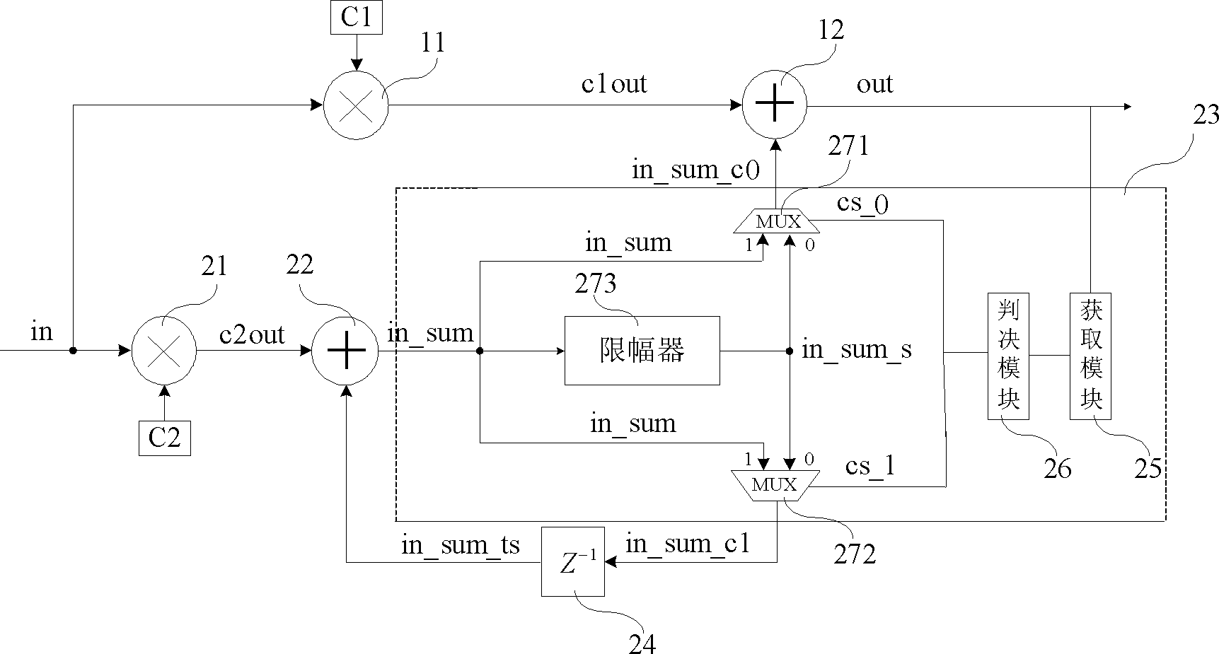
[0021] Aiming at the defects of the loop filter circuit in the prior art, the embodiment of the present invention provides a loop filter of a phase-shift keying demodulation circuit, specifically as image 3 As shown, the loop filter provided by the embodiment of the present invention mainly includes a first circuit and a second circuit, wherein t...


PUM


Abstract

The invention provides a loop filter of phase shift keying demodulation circuits, a phase shift keying demodulation circuit and a signal processing method. The loop filter comprises a first circuit and a second circuit, a first multiplier and a first summator are arranged on the first circuit, a second multiplier, a second summator, a unit delayer and an amplitude limiting device are disposed on the second circuit, an output end of the second multiplier is connected with a first input end of the second summator, an output end of the second summator is connected with an input end of the amplitude limiting device, an output end of the amplitude limiting device is respectively connected with a second input end of the first summator and an input end of the unit delayer, and the amplitude limiting device is used for selecting whether an amplitude limiting value is output to the second input end of the first summator and whether the amplitude limiting value is output to the input end of the unit delayer according to an output value of the first summator and a pre-set threshold value. By means of the technical scheme, the demodulation performance of the phase shift keying demodulation circuit can be improved.

Description

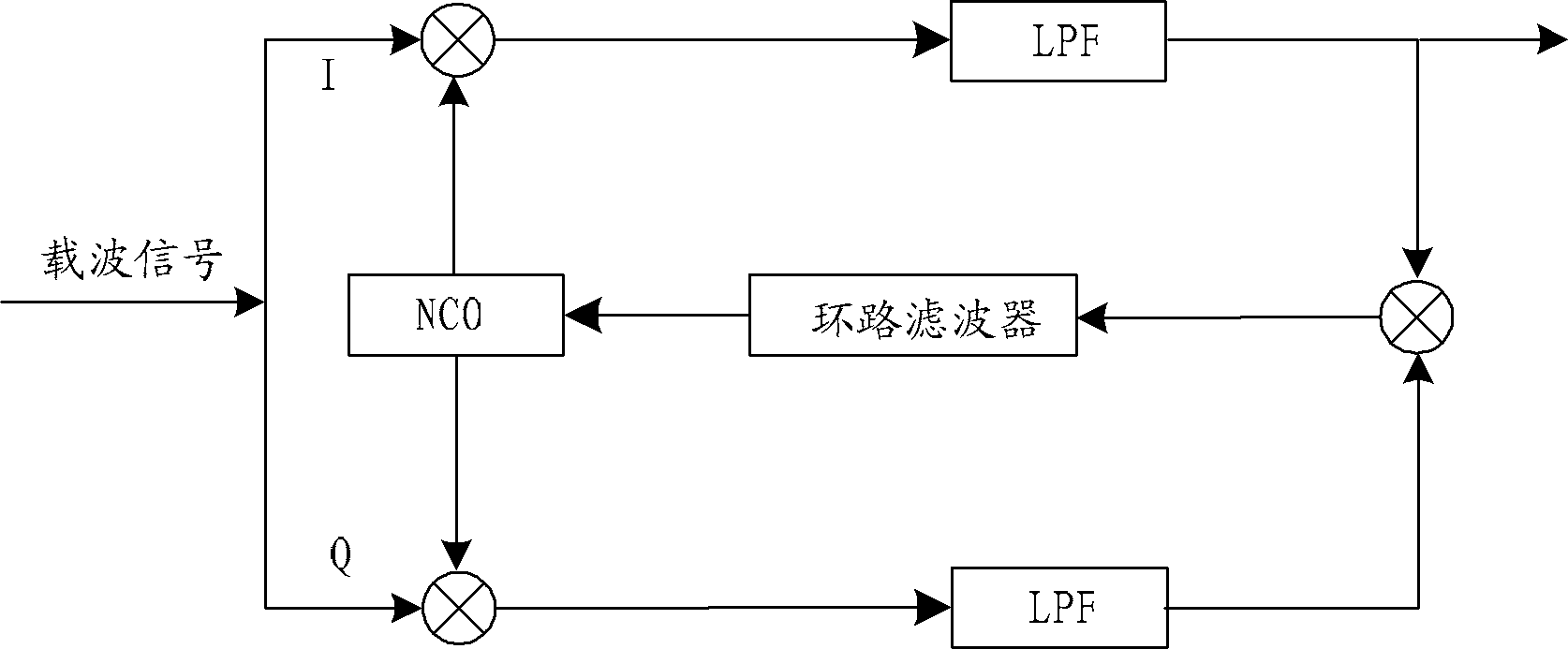
technical field [0001] The invention relates to signal demodulation technology, in particular to a loop filter circuit of a phase shift keying demodulation circuit and a phase shift keying demodulation circuit, belonging to the technical field of signal processing. Background technique [0002] In power line carrier communication technology, phase shift keying (Phase Shift Keying, hereinafter referred to as: PSK) technology is usually used for demodulation of communication signals. figure 1 The PSK demodulation circuit in the prior art is given, wherein the received carrier signal is divided into two paths of in-phase (I part) and quadrature (Q part), which are first connected with a numerically controlled oscillator (Numerical Controlled Oscillator, hereinafter referred to as: NCO ) module output local quadrature signals are multiplied, and then output after filtering through a low pass filter (Low Pass Filter, hereinafter referred to as: LPF); the two signals output by the...

Claims


Application Information

Patent Timeline
Patent Type & Authority Patents(China)
IPC IPC(8): H03H17/02H04L27/22
Inventor 张伟陈光胜谷志坤
Owner SHANGHAI EASTSOFT MICROELECTRONICS
Learn More