
Apparatus and method for time synchronization and reception apparatus of OFDM system

a technology of orthogonal frequency division multiplexing and reception apparatus, applied in multi-frequency code systems, digital transmission, amplitude demodulation, etc., can solve the problems of affecting affecting the detection performance of frames and symbols, and increasing errors of frame and symbol synchronization. , to achieve the effect of improving the timing resolution of synchronization, improving the detection performance of frames and symbols, and improving the reception performance of data

Inactive Publication Date: 2010-06-24
ELECTRONICS & TELECOMM RES INST
View PDF8 Cites 17 Cited by
  • Summary
  • Abstract
  • Description
  • Claims
  • Application Information

AI Technical Summary

Benefits of technology

[0010]The present invention has been made in an effort to provide an apparatus and a method for time synchronization and a reception apparatus of an orthogonal frequency division multiplexing (OFDM) system that can increase accuracy of detection of a frame and synchronization and improve demodulation performance in a channel environment in which a vehicle moves at a high speed.
[0014]According to an embodiment of the present invention, it is possible to improve timing resolution of synchronization by using a master clock that is four times faster than a digital sampling signal, and by using the master clock, it is possible to remarkably improve the detection performance of a frame and a symbol and the reception performance of data in a vehicle communication system using an OFDM scheme.

Problems solved by technology

Since the vehicle communication system is designed assuming a wireless channel at a stoppage speed or a pedestrian speed, the performance of the system is remarkably deteriorated in a channel environment in which the vehicle moves at a high speed.
The short training sequence and the long training sequence are designed on the basis of a channel environment having a low movement speed, so it is difficult to detect an accurate frame and accurate synchronization and estimate a channel in the channel environment in which the vehicle moves at the high speed.
In this case, since resolution is insufficient in acquiring a sample having maximum reception energy in the reception device, errors of a frame and symbol synchronization increase.
When the errors of the frame and symbol synchronization increase, a demodulation function is performed by using a sample having low reception energy value, thereby deteriorating demodulation performance.

Method used


Image

  • Apparatus and method for time synchronization and reception apparatus of OFDM system
  • Apparatus and method for time synchronization and reception apparatus of OFDM system
  • Apparatus and method for time synchronization and reception apparatus of OFDM system

Examples


first embodiment

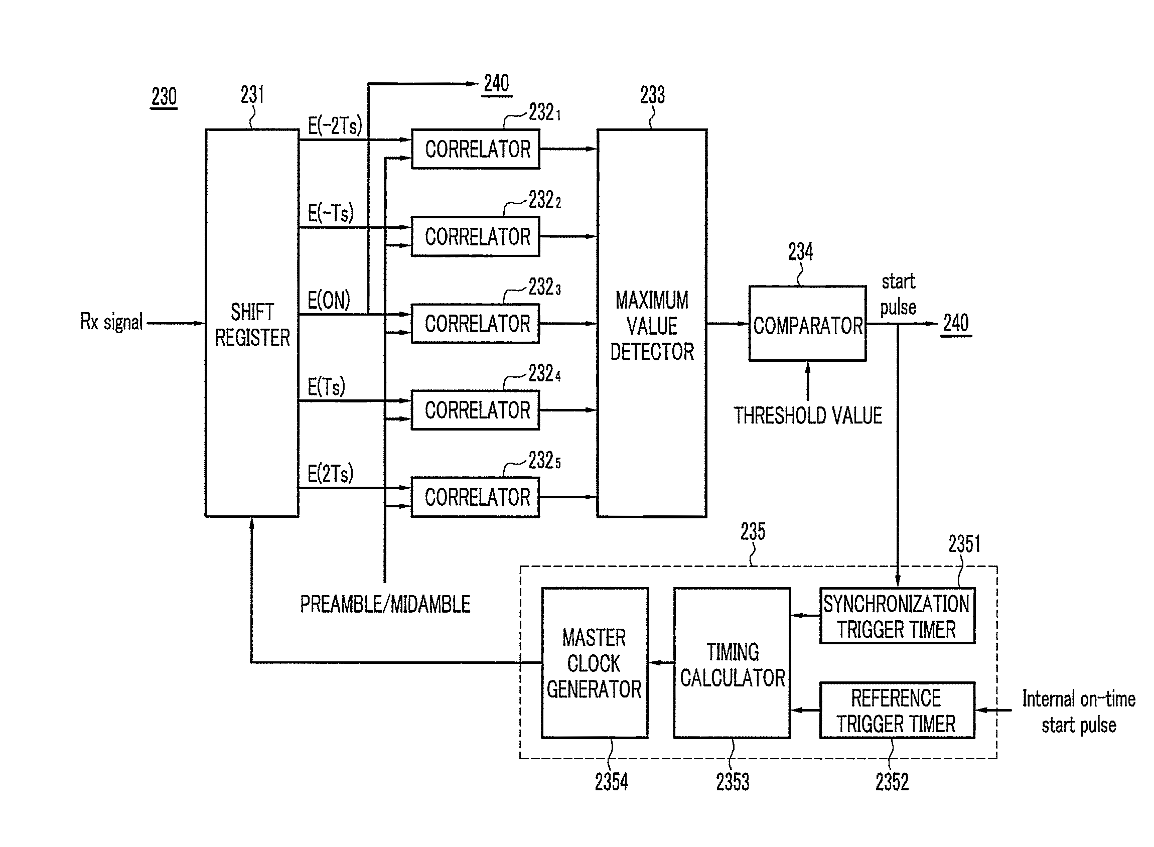
[0042]FIG. 4 is a block diagram illustrating a time synchronizer according to the present invention.

[0043]Referring to FIG. 4, the time synchronizer 230 includes a shift register 231, a plurality of correlators 2321 to 2325, a maximum value detector 233, a comparator 234, and a master clock controller 235.

[0044]The shift register 231 oversamples the digital sample signal Rx signal using a master clock having a frequency at least four times higher than a minimum sampling frequency, sets one of the oversampled signals to an on-time signal, and shifts signals oversampled by −2Ts, −Ts, Ts, and 2Ts on the basis of the on-time signal, and outputs the on-time signal E(on), signals shifted E(−2Ts), E(−Ts), E(Ts), and E(Ts).

[0045]The plurality of correlators 2321 to 2325 correlate the previously known preamble with the corresponding signal among the signals E(−2Ts), E(−Ts), E(Ts), and E(Ts) outputted from the shift register 231 to calculate a correlation value. At this time, the midamble may...

second embodiment

[0054]FIG. 5 is a block diagram illustrating a time synchronizer according to the present invention.

[0055]Referring to FIG. 5, a time synchronizer 230′ is similar to the time synchronizer 230 according to the first embodiment of the present invention, except that the time synchronizer 230′ includes a signal selector 236 instead of the master clock controller 235. However, unlike the first embodiment, a maximum value detector 233′ detects the maximum energy value among the correlation values calculated by the plurality of correlators 2321 to 2325 and transmits an index corresponding to the signal having the maximum energy value to the signal selector 236.

[0056]The signal selector 236 receives the signals E(−2Ts), E(−Ts), Es(on), E(Ts), and E(2Ts) outputted from the shift register 231 and selects a signal corresponding to the index transmitted from the maximum detector 233′ among the received signals E(−2Ts), E(−Ts), Es(on), E(Ts), and E(2Ts), and outputs the selected signal to the fr...


PUM


Abstract

An apparatus for time synchronization of an orthogonal frequency division multiplexing (OFDM) system oversamples a received signal using a master clock having a frequency at least four times higher than a minimum sampling frequency in a transmission apparatus, sets one of a plurality of oversampled signals to an on-time signal, and shifts each of the remaining oversampled signals by a predetermined time on the basis of the on-time signal. The apparatus for time synchronization calculates a correlation value by correlating each of the shifted signals and the on-time signal with a previously known signal, detects a maximum energy value among the calculated correlation values, and detects a start point of a frame by comparing the maximum energy value with a predetermined threshold value.

Description

CROSS-REFERENCE TO RELATED APPLICATION[0001]This application claims priority to and the benefit of Korean Patent Application No. 10-2008-0130975 filed in the Korean Intellectual Property Office on Dec. 22, 2008, the entire contents of which are incorporated herein by reference.BACKGROUND OF THE INVENTION[0002](a) Field of the Invention[0003]The present invention relates to an apparatus and a method for time synchronization and a reception apparatus of an orthogonal frequency division multiplexing (OFDM) system.[0004](b) Description of the Related Art[0005]A vehicle communication system that provides vehicle-to-vehicle communication and vehicle-to-infrastructure communication on the basis of a vehicle moving at high speed uses an orthogonal frequency division multiplexing (hereinafter referred to as “OFDM”) scheme as a wireless LAN technology.[0006]Since the vehicle communication system is designed assuming a wireless channel at a stoppage speed or a pedestrian speed, the performance...

Claims


Application Information

Patent Timeline
IPC IPC(8): H04L27/06H04L7/00
CPCH04L25/068H04L27/2695H04L27/2675H04L27/2656H04L27/2644H04L27/265
Inventor OH, HYUN SEOCHOI, HYUN KYUNKIM, SANGINHONG, DAEKIKWAK, DONG YONGPARK, JONG-HYUN
Owner ELECTRONICS & TELECOMM RES INST
Learn More