Optical identification as well as method and device for modulating and demodulating the same

一种光标识、标识的技术,应用在通信领域,能够解决光标识所需频率标识不足、波长冲突等问题,达到降低解调难度、降低功耗、降低互相干扰的效果

Active Publication Date: 2008-12-24
HUAWEI TECH CO LTD
View PDF0 Cites 18 Cited by
  • Summary
  • Abstract
  • Description
  • Claims
  • Application Information

AI Technical Summary

Problems solved by technology

[0020] The embodiment of the present invention provides an optical identification, modulation and demodulation method and device, which solves the problem of insufficient frequency identification and wavelength conflict in the prior art optical identification

Method used


Image

  • Optical identification as well as method and device for modulating and demodulating the same
  • Optical identification as well as method and device for modulating and demodulating the same
  • Optical identification as well as method and device for modulating and demodulating the same

Examples


Embodiment Construction

[0063] The following will clearly and completely describe the technical solutions in the embodiments of the present invention with reference to the accompanying drawings in the embodiments of the present invention. Obviously, the described embodiments are only some, not all, embodiments of the present invention. Based on the embodiments of the present invention, all other embodiments obtained by persons of ordinary skill in the art without creative efforts fall within the protection scope of the present invention.

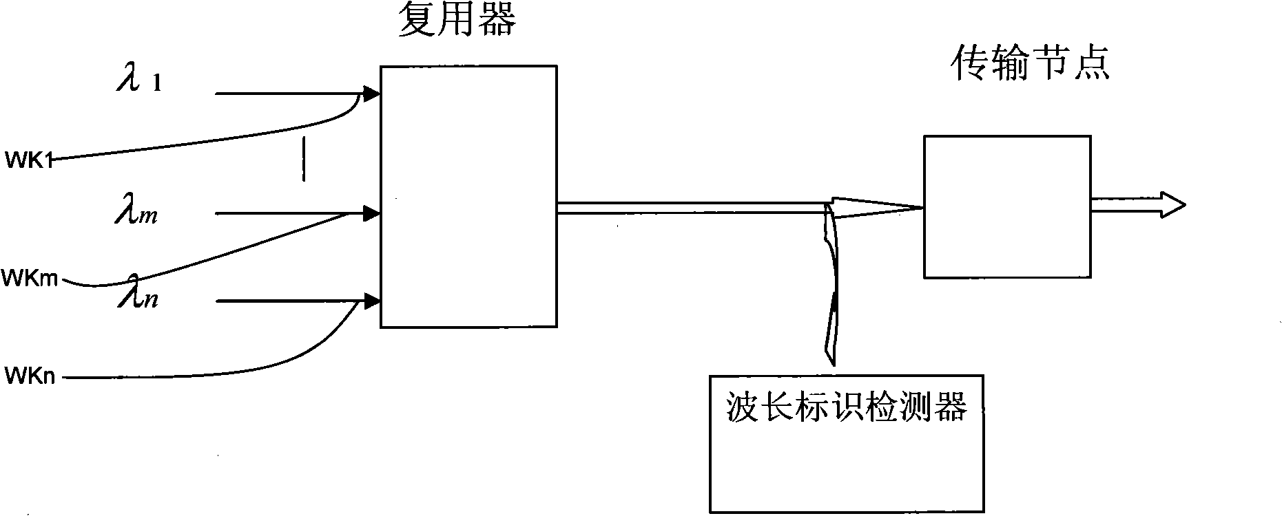
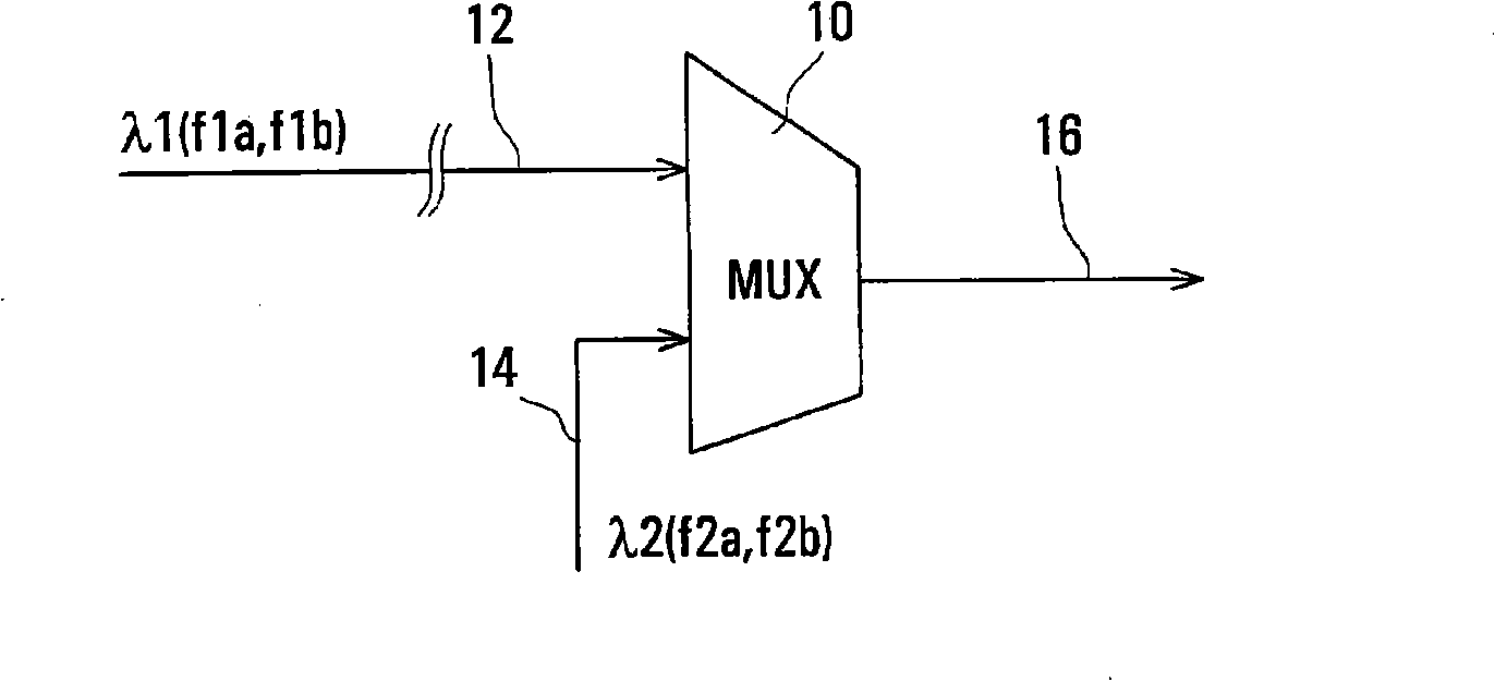
[0064] The embodiment of the present invention adopts the identification that the frequency part and the interval time appear alternately, different frequencies are used to distinguish different wavelengths, and the interval time in the middle of the frequency can be the same or different; the same frequency is used for the same wavelength of different nodes, but The interval between frequencies is different.

[0065] Such as Figure 5 As shown, it is a schematic ...


PUM


Abstract

The embodiment of the invention provides an optical marker, a modulation and demodulation method and a device. The modulation method comprises the following steps: a marker that frequency and interval time appear alternately and periodically is generated; enlargement processing is performed to the marker; the marker after the enlargement processing is modulated to an optical signal. By adopting the marker that the frequency part and the interval time appear alternately and periodically is generated, discrimination is performed to the different wave lengths by using different frequencies; the identical wave length of different nodes uses identical frequency and different interval time. Therefore, the purpose that numerous available markers can be provided by using a smaller amount of frequency numbers can be realized, and the unique marker of each wave length of the entire network is only required to be equal to the frequency number of the wave length number of the network; and even ifthe wavelength conflict occurs, the phenomenon whether the wavelength conflict occurs or not can be judged through the detected marking conditions.

Description

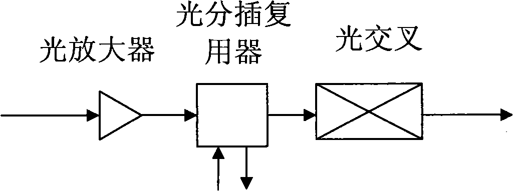
technical field [0001] The present invention relates to the field of communication technology, in particular to an optical identification and modulation and demodulation method and device. Background technique [0002] With the development of optical transport technology, the optical transport network is developing towards an all-optical configurable network, and the network topology is also developing towards a MESH (grid) network, and the network scale is getting larger and larger. Since the wavelength channel is transmitted in an all-optical state in the network, the channel information cannot be obtained by extracting the channel overhead through photoelectric conversion at the intermediate node. In this case, it becomes very difficult to identify the fiber connection relationship, wavelength channel trace, performance, etc. questions such as figure 1 Shown is a schematic diagram of an all-optical transmission node. [0003] In order to solve the above problems, an opt...

Claims


Application Information

Patent Timeline
Patent Type & Authority Applications(China)
IPC IPC(8): H04L27/26H04B10/00
CPCH04J14/0258H04J14/0263H04J14/0276H04J14/0298
Inventor 申书强
Owner HUAWEI TECH CO LTD
Why Eureka
Try Eureka