Transverse and longitudinal adjusting auxiliary device for butt joint installation of station equipment
A technology of docking installation and longitudinal adjustment, which is applied to workbenches, manufacturing tools, hand-held tools, etc., to achieve the effects of improving installation efficiency, facilitating rapid adjustment, and low maintenance costs
Inactive Publication Date: 2022-06-10
梁云招
View PDF0 Cites 1 Cited by
- Summary
- Abstract
- Description
- Claims
- Application Information
AI Technical Summary
Problems solved by technology
The above-mentioned work of moving and adjusting the position of the equipment to be installed is usually manually moved by the installer, which requires a large amount of manpower, and the equipment is generally heavy, which is not conducive to quickly completing the docking installation in a short time
Method used
View moreImage
Smart ImageViewing Examples
Examples
Embodiment Construction
Login to View More PUM
 Abstract
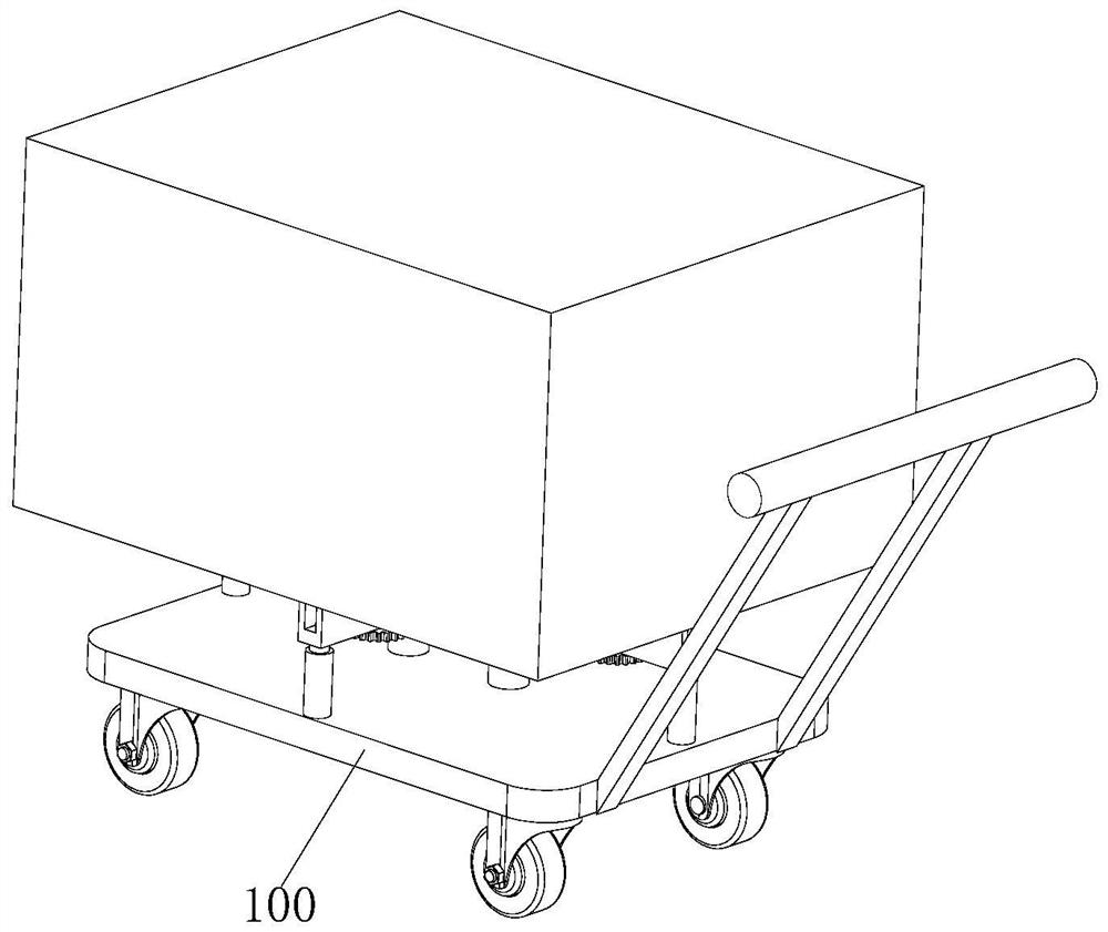
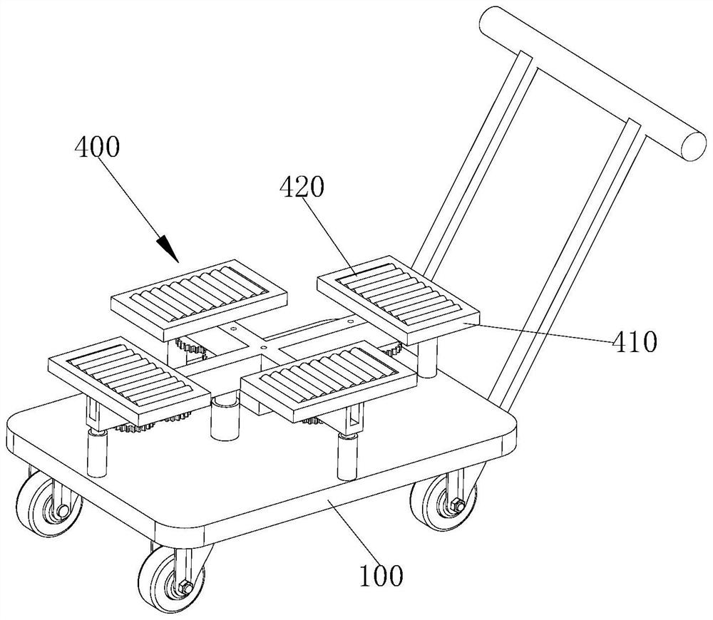
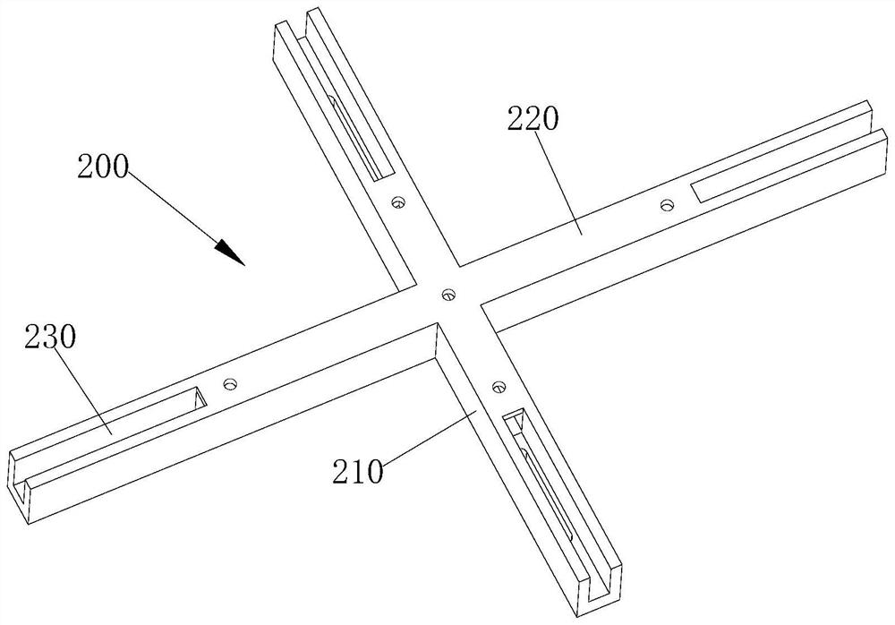
The invention relates to the technical field of equipment adjusting auxiliary devices, in particular to a transverse and longitudinal adjusting auxiliary device for butt joint installation of station equipment, which comprises a cart, supporting pieces are connected to two ends of the top surface of the cart and two sides of the top surface of the cart, and a cross-shaped bearing frame is fixedly connected to the top surfaces of the multiple supporting pieces. The cross-shaped bearing frame comprises a transverse beam and a longitudinal beam, the middle of the transverse beam is fixedly connected with the middle of the longitudinal beam, moving blocks are slidably connected to the two ends of the transverse beam and the two ends of the longitudinal beam, brackets are connected to the tops of the moving blocks, and bidirectional moving mechanisms for driving the moving blocks at the corresponding positions to move are arranged on the bottom faces of the two ends of the transverse beam and the bottom faces of the two ends of the longitudinal beam. A motor drives a driving shaft to rotate, so that the driving shaft drives a positioning shaft on a longitudinal beam to rotate through a belt, a transmission gear at the bottom of the positioning shaft is meshed with an adjacent transmission gear to rotate, and a moving shaft drives a moving block to reciprocate in a sliding groove; the two moving blocks on the longitudinal beam are matched to drive the mechanical equipment to move in a longitudinal reciprocating mode.
Description
technical field [0001] The invention relates to the technical field of equipment adjustment auxiliary devices, in particular to a horizontal and vertical adjustment auxiliary device for docking installation of station equipment. Background technique [0002] A processing line in the factory contains multiple stations, and each station is equipped with different mechanical equipment for different aspects of product processing. In the process of installing mechanical equipment on a certain assembly line, it is often necessary to move a piece of equipment to be installed to the side of the installed equipment, and adjust the position of the equipment to be installed by moving horizontally and vertically, so as to facilitate the connection holes on the equipment to be installed or The connecting clip is docked and fixed with the installed equipment. When the connecting clip of the equipment to be installed is inserted into the installed equipment through vertical movement, some...
Claims
Login to View More Application Information
Patent Timeline
 Patent Type & Authority Applications(China)
IPC IPC(8): B25H1/04B25H1/08B25H1/16B25B27/00
CPCB25H1/16B25H1/08B25H1/04B25B27/00
Inventor 梁云招
Owner 梁云招
Features
- R&D
- Intellectual Property
- Life Sciences
- Materials
- Tech Scout
- Unparalleled Data Quality
- Higher Quality Content
- 60% Fewer Hallucinations
Learn More Browse by: Latest US Patents, China's latest patents, Technical Efficacy Thesaurus, Application Domain, Technology Topic, Popular Technical Reports.
© 2025 PatSnap. All rights reserved.Legal|Privacy policy|Modern Slavery Act Transparency Statement|Sitemap|About US| Contact US: help@patsnap.com


