Power cable winding and unwinding equipment and using method thereof

A power cable rewinding and unwinding technology, which is applied in the field of power cable rewinding and unwinding equipment, can solve problems such as cable shedding, increased cable rewinding thickness, and insufficient rewinding of cables

Active Publication Date: 2022-06-17
GANSU SHINING SCI & TECH
View PDF9 Cites 0 Cited by
  • Summary
  • Abstract
  • Description
  • Claims
  • Application Information

AI Technical Summary

Problems solved by technology

[0003] The size of the rewinding device/equipment in the above existing documents is fixed, the length of the rewinding area along the axial direction is determined, and it can only rewind the power cable within a certain length along the axial direction. When the power cable that needs to be

Method used


Image

  • Power cable winding and unwinding equipment and using method thereof
  • Power cable winding and unwinding equipment and using method thereof
  • Power cable winding and unwinding equipment and using method thereof

Examples


Example Embodiment

[0027]实施例一

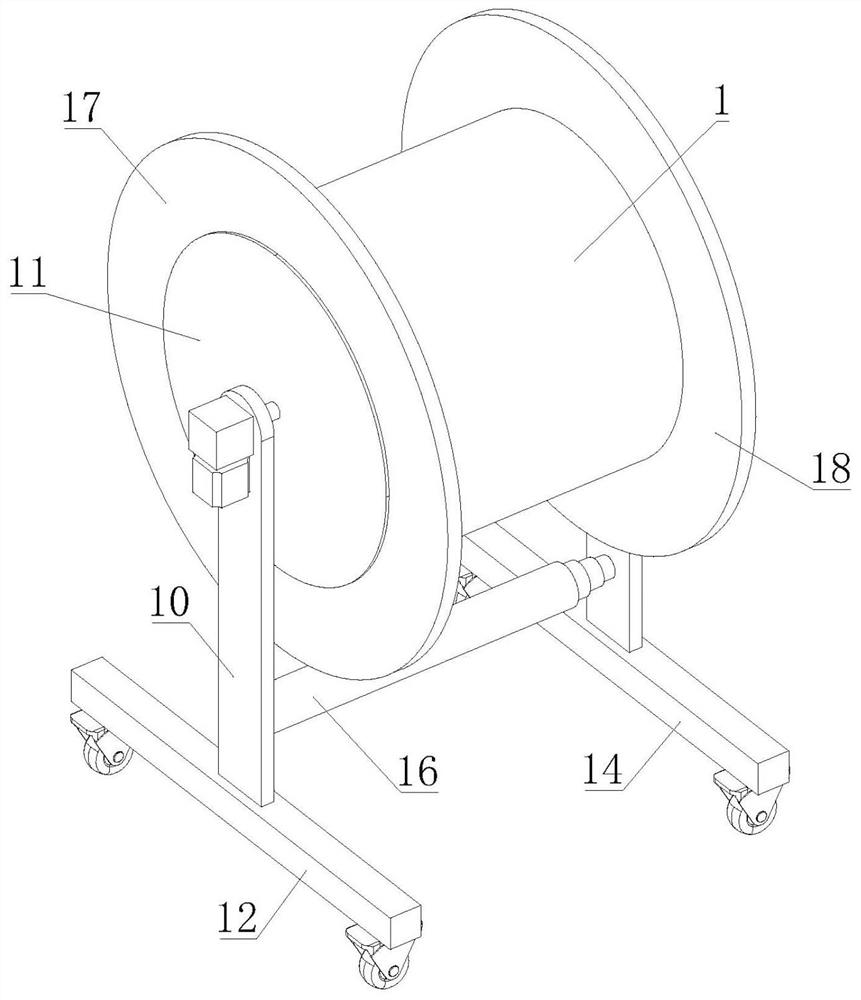
[0028]如图1-4所示,本发明提出的一种电力线缆收放卷设备,包括连接轴组件、支撑组件a、支撑组件b和直径逐渐减小的多个圆形的滚筒;

[0029]多个滚筒沿直径逐渐减小的顺序依次分布,任意两个滚筒沿轴向滑动连接,连接轴组件包括连接轴a72和连接轴b73,连接轴a72与直径最大的滚筒连接,该直径最大的滚筒内侧设置有用于驱动多个滚筒通过相对运动实现同步伸长或同步收缩的调节机构,连接轴b73与直径最小的滚筒连接,连接轴a72转动设置在支撑组件a上,连接轴b73转动设置在支撑组件b上,支撑组件a或支撑组件b上设置有用于驱动连接轴组件转动的动力装置。调节机构和动力装置均能通过设置控制开关的方式进行控制。

[0030]本实施例能根据需要收卷的线缆长度进行自适应调节以充分地、有效地、整洁地收卷线缆。通过调节机构能调节多个滚筒同步伸长或同步收缩,从而实现滚筒上用于收卷电力线缆的区域的长度的同步调节。当需要收卷的电力线缆较长时,需要将滚筒上的收卷区域调长;收卷区域调节完毕后,通过动力装置驱动连接轴组件正转,连接轴组件带动滚筒转动,进行电力线缆的收卷。在需要放卷电力线缆时,动力装置能驱动连接轴组件反转,连接轴组件带动滚筒反转,从而实现电力线缆的放卷。

Example Embodiment

[0031]实施例二

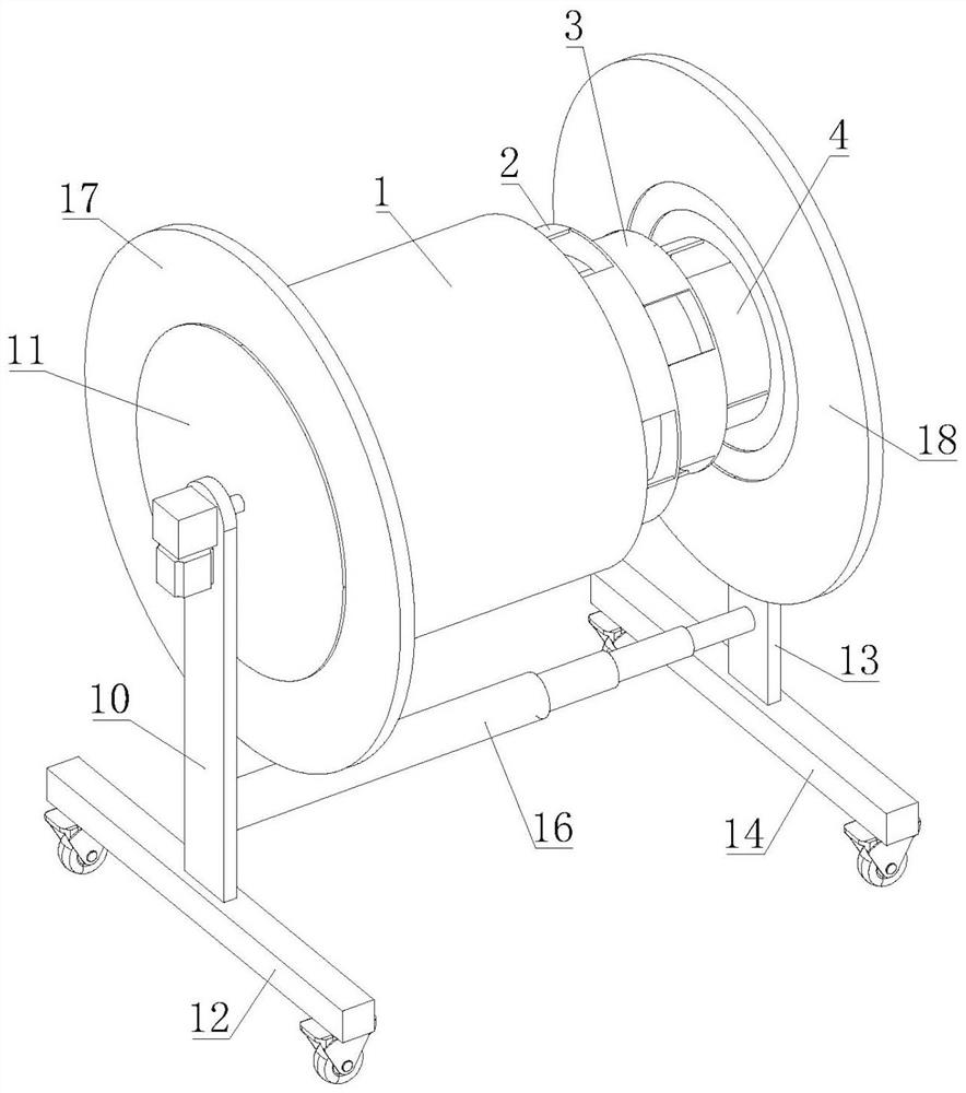
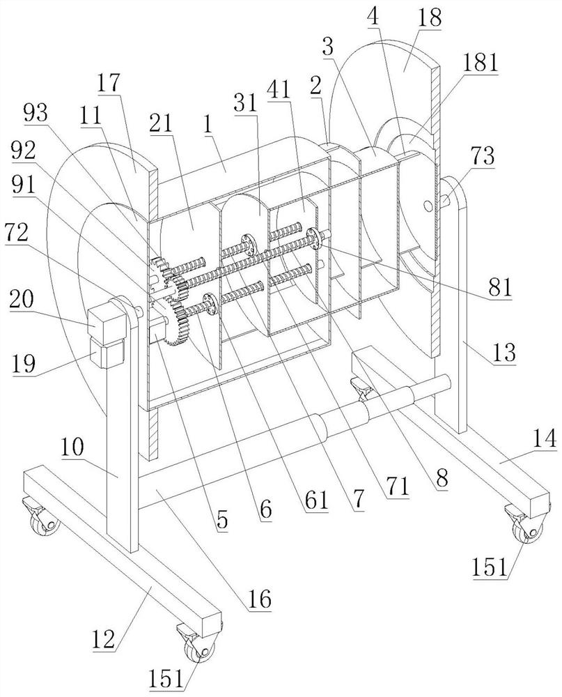
[0032]如图1-4所示,本发明提出的一种电力线缆收放卷设备,相较于实施例一,本实施例中,滚筒共设置有四个,四个滚筒分别为直径依次减小的一级滚筒1、二级滚筒2、三级滚筒3和四级滚筒4,一级滚筒1一端为侧板a11,二级滚筒2朝向侧板a11的一端为侧板b21,二级滚筒2具有滑动板部a,三级滚筒3朝向侧板b21的一端为侧板c31,三级滚筒3具有滑动板部b,四级滚筒4朝向侧板c31的一端为侧板d41,四级滚筒4具有滑动板部c;一级滚筒1具有供滑动板部a穿过且与滑动板部a滑动连接的导向孔a101,一级滚筒1具有供滑动板部b穿过且与滑动板部b滑动连接的导向孔b102,一级滚筒1具有供滑动板部c穿过且与滑动板部c滑动连接的导向孔c103;二级滚筒2具有供滑动板部b穿过且与滑动板部b滑动连接的导向孔d201,二级滚筒2具有供滑动板部c穿过且与滑动板部c滑动连接的导向孔e202;三级滚筒3具有供滑动板部c穿过且与滑动板部c滑动连接的导向孔f301;侧板a11与连接轴a72连接,四级滚筒4与连接轴b73连接。多个滚筒之间能进行相互滑动,能实现彼此之间滑动的导向,使得多个滚筒能顺畅的滑动,且能起到充分的支撑作用和线缆绕收作用,能对线缆进行稳定牢靠的绕收。滚筒的数量可根据实际需求进行灵活设置,模块化程度高。

[0033]调节机构包括电机5、丝杆a6、丝杆螺母a61、丝杆b7、丝杆螺母b71、丝杆c8、丝杆螺母c81、齿轮a91、齿轮b92和齿轮c93,电机5设置在侧板a11上,电机5与丝杆a6驱动连接,丝杆a6与丝杆螺母a61螺纹连接,丝杆螺母a61与侧板b21连接,丝杆b7与丝杆螺母b71螺纹连接,丝杆螺母b71与侧板c31连接,丝杆c8与丝杆螺母c81螺纹连接,丝杆螺母c81与侧板d41连接,丝杆a6、丝杆b7和丝杆c8均与一级滚筒1转动连接,齿轮a91设置在丝杆a6上,齿轮b92设置在丝杆b7上,齿轮c93设置在丝杆c8上,齿轮a91、齿轮b92和齿轮c93依次啮合连接,齿轮a91、齿轮b92和齿轮c93的齿数依次减少,从而能使丝杆a6、丝杆b7和丝杆c8的转速依次增大,侧板b21、侧板c31和侧板d41的移动速度依次增大,能实现多个滚筒的同步伸出或收缩,仅使用一个电机5即能实现上述过程,更加节能,结构紧凑,占用空间小;侧板b21、侧板c31和侧板d41上均...

Example Embodiment

[0042]实施例三

[0043]如图1-3所示,本发明提出的一种电力线缆收放卷设备,相较于实施例一,本实施例中,动力装置包括驱动电机19和减速机20,驱动电机19和减速机20均设置在支撑组件a上或均设置在支撑组件b上,驱动电机19输出端与减速机20输入端连接,当驱动电机19和减速机20均设置在支撑组件a上时,减速机20输出端与连接轴a72连接,当驱动电机19和减速机20均设置在支撑组件b上时,减速机20输出端与连接轴b73连接,驱动电机19的输出端能正反转,能在减速机20的传动作用下驱动连接轴a72或连接轴b73转动,实现电力线缆的绕收或放卷,节省人工,省时省力。

[0044]如图1-3所示,支撑组件a包括支架a10和底架a12,连接轴a72转动设置在支架a10上,支架a10设置在底架a12上,支撑组件b包括支架b13和底架b14,连接轴b73转动设置在支架b13上,支架b13设置在底架b14上;底架a12和底架b14底部均设置有脚轮151,方便在调节多个滚筒的伸出或收缩程度时进行移动,支撑组件a和支撑组件b均起到支撑作用,保障设备能顺畅的收放卷线缆。

[0045]如图1-2所示,支架a10和支架b13之间连接有伸缩杆16,伸缩杆16包括多个依次滑动连接的滑动筒,伸缩杆16能对支撑组件a和支撑组件b的间距调节进行导向和支撑,提高整个设备的稳定性。


PUM


Abstract

The invention relates to the field of cable winding, in particular to power cable winding and unwinding equipment and a using method thereof. The device comprises a connecting shaft assembly, a supporting assembly a, a supporting assembly b and a plurality of circular rollers with the diameters gradually reduced. The multiple rollers are sequentially distributed in the sequence that the diameters are gradually reduced, any two rollers are in sliding connection in the axial direction, the connecting shaft assembly comprises a connecting shaft a and a connecting shaft b, and the connecting shaft a is connected with the roller with the largest diameter; the inner side of the roller with the largest diameter is provided with an adjusting mechanism used for driving the multiple rollers to synchronously stretch or contract through relative movement, the connecting shaft b is connected with the roller with the smallest diameter, the connecting shaft a is rotationally arranged on the supporting assembly a, and the connecting shaft b is rotationally arranged on the supporting assembly b. A power device used for driving the connecting shaft assembly to rotate is arranged on the supporting assembly a or the supporting assembly b. According to the cable winding device, self-adaptive adjustment can be conducted according to the length of a cable needing to be wound so that the cable can be wound sufficiently, effectively and neatly.

Description

Technical field [0001] The invention relates to the field of cable rewinding, in particular to a power cable rewinding and unwinding device and a method for using the same. Background technique [0002] In the process of electric power construction, it is usually necessary to reel up the used cables, so cable reeling equipment is used. Chinese Patent Publication No. CN114261840A discloses a power cable winding device, and Chinese Patent Publication No. CN110697504B discloses a compact power cable winding device. [0003] The size of the rewinding device / equipment in the above-mentioned existing documents is fixed, the length of the rewinding area along the axial direction is determined, and it can only rewind the power cables within a certain length along the axial direction. When the length exceeds the maximum winding length, the thickness of the cable winding will increase, and the cable will easily fall off from the axial ends of the device / equipment, resulting in insuff...

Claims


Application Information

Patent Timeline
IPC IPC(8): B65H75/24B65H75/44
CPCB65H75/241B65H75/4465B65H75/4486B65H2701/34
Inventor 刘晓光蔡玺张世元张文轩刘熠
Owner GANSU SHINING SCI & TECH
Why Eureka
Try Eureka