Oily PVDF diaphragm coating system

A diaphragm, oil-based technology, applied in the field of oil-based PVDF diaphragm coating system, can solve problems such as difficult storage

Pending Publication Date: 2019-11-12
常州恒锌禹晟智能装备股份有限公司
View PDF0 Cites 0 Cited by
  • Summary
  • Abstract
  • Description
  • Claims
  • Application Information

AI Technical Summary

Problems solved by technology

[0004] Although it can greatly reduce heat loss, it is not easy to store;

Method used


Image

  • Oily PVDF diaphragm coating system
  • Oily PVDF diaphragm coating system

Examples


Embodiment Construction

[0035] The present invention is described in further detail now in conjunction with accompanying drawing. These drawings are all simplified schematic diagrams, which only illustrate the basic structure of the present invention in a schematic manner, so they only show the configurations related to the present invention.

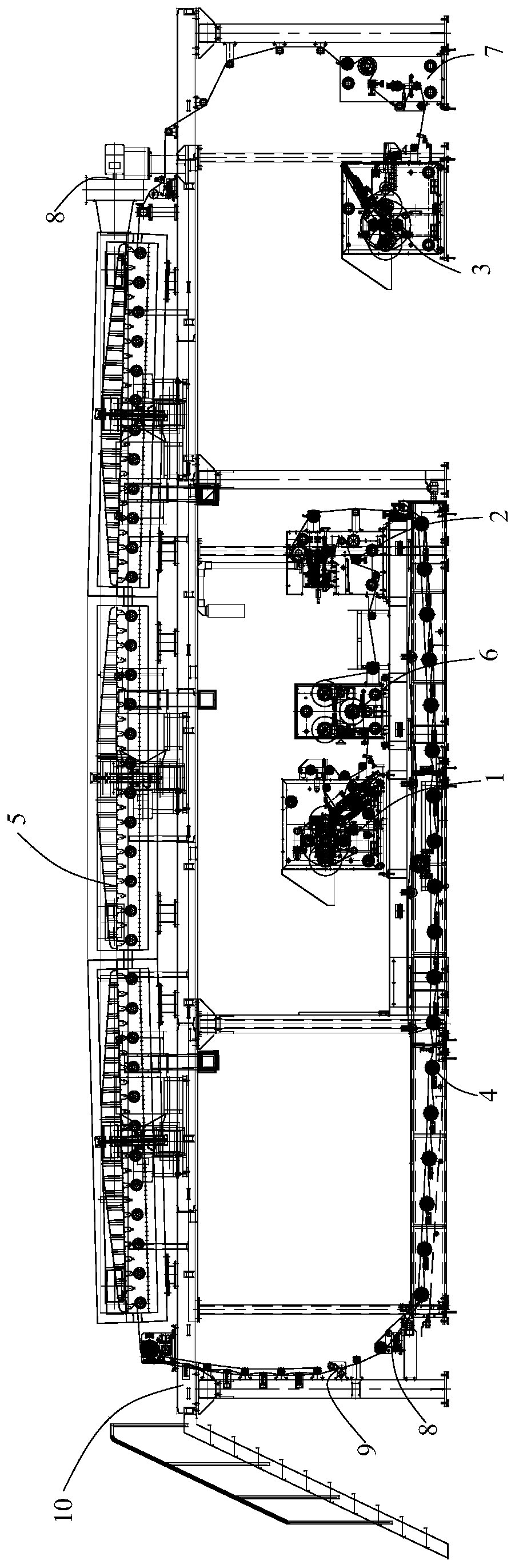
[0036] Such as figure 1 with 2 Shown, a kind of oily PVDF diaphragm coating system comprises: unwinder 1, coating machine 2 and winding machine 3 arranged along PVDF diaphragm traveling direction, described oily PVDF diaphragm coating system also comprises a water tank 4 , and the unwinding machine 1 and the coating machine 2 are fixed on the water tank 4, wherein the base material can be unwinded by the unwinding machine 1, coated by the coating machine 2, and coated by the coating machine 2 in turn. The water tank 4 makes the glue solidify and the winder 3 is housed.

[0037] Wherein, the unwinder 1, the coater 2 and the winder 3 are located on a horizont...


PUM


Abstract

The invention relates to an oily PVDF diaphragm coating system. The oily PVDF diaphragm coating system comprises an unwinder, a coater and a winder which are arranged in the direction of travel of a PVDF diaphragm. The oily PVDF diaphragm coating system further comprises a water tank, wherein the unwinder and the coater are fixed on the water tank. A substrate can be unwinded by the unwinder and then coated by the coater, the water tank is used for diluting glue, and the substrate is stored by the winder. By the adoption of the oily PVDF diaphragm coating system with convenient feeding and storage functions, by arranging the unwinder, the coater and the winder, the unwinding, coating and winding effects are achieved. By arranging the water tank, NMP in the coating glue is diluted. Becausethe water tank is located under the unwinder, the coater and the winder, loop feed is formed, and the direct contact with the glue surface of the substrate is avoided.

Description

technical field [0001] The invention relates to an oily PVDF diaphragm, in particular to an oily PVDF diaphragm coating system. Background technique [0002] The patent number is CN2018201171966, and the name is a production line for preparing PVDF diaphragm battery pole piece components by dry method. Among them, the present invention relates to the field of energy storage technology, and provides a production line for dry method preparing PVDF diaphragm battery pole piece components, including electromagnetic wave heating device, the electromagnetic wave heating device has a heating section for the PVDF diaphragm to pass through; the production line also includes a driving device for driving the PVDF diaphragm through the heating section, and is used to place the positive and negative electrodes on the Manipulators on two opposite surfaces of the PVDF membrane, the manipulators are located at the exit of the heating zone. The present invention heats the PVDF diaphragm by ...

Claims


Application Information

Patent Timeline
Patent Type & Authority Applications(China)
IPC IPC(8): B05C9/12B05C9/14
CPCB05C9/12B05C9/14
Inventor 舒星火
Owner 常州恒锌禹晟智能装备股份有限公司
Why Eureka
Try Eureka