Protective device for lenses of micro-lens myopic glasses
A technology of spectacle lenses and protective devices, applied in the directions of glasses/goggles, instruments, optics, etc., can solve the problems of difficulty, processing, and expensive lenses, and achieve the effect of easy purchase
- Summary
- Abstract
- Description
- Claims
- Application Information
AI Technical Summary
Problems solved by technology
Method used
Image
Examples
Embodiment 1
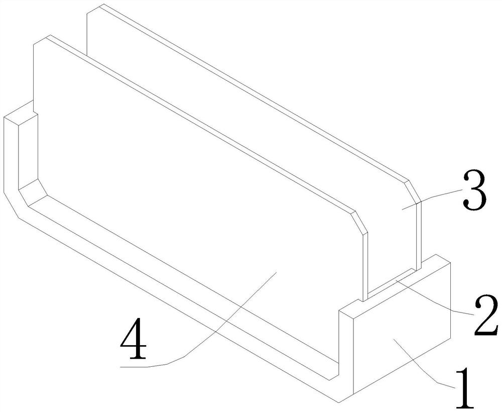
[0036] like figure 1 , 2 , 3, 4, 5, 6, and 7, the present embodiment provides a protection device for the lens of microlens myopia glasses, including a frame body 1, and the above-mentioned frame body 1 is provided with a lens protection groove 103 and is used for installing the microlens myopia. The lens mounting groove 102 of the lens 3; the lens protection groove 103 is provided with a protective lens 4 therein.
[0037] In this embodiment, a frame body 1 is included, wherein the frame body 1 can be a common spectacle frame, which is convenient for purchase during production and can also be modified for common spectacle frames.
[0038] The above-mentioned frame body 1 is provided with a lens protection groove 103 and a lens installation groove 102 for installing the microlens myopia lens 3. The above-mentioned lens protection groove 103 is provided with a protective lens 4, and the protective lens 4 can be a common glass lens or resin lens. The protective lens 4 is compo...
Embodiment 2
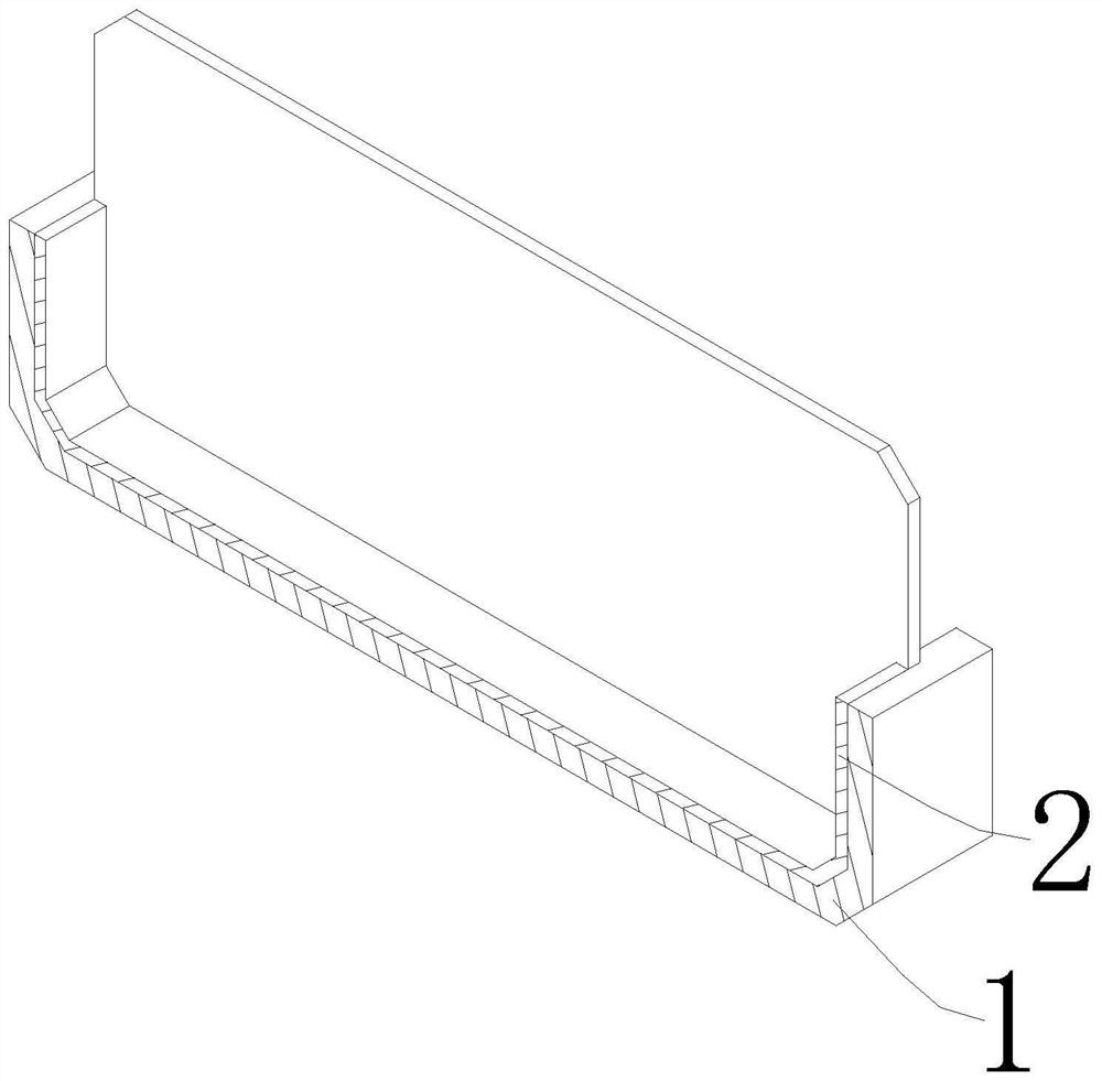
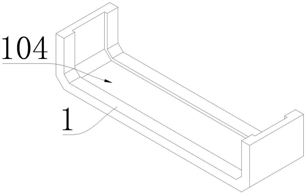
[0041] like figure 1 , 2 , 3, 4, 5, 6, and 7, in some implementations of this embodiment, the above-mentioned mirror frame body 1 includes a through groove 104 and a width adjustment piece 2, and the above-mentioned width adjustment piece 2 is located in the above-mentioned through groove 104, and the above-mentioned The width adjustment sheet 2 and the inner side wall of the through groove 104 respectively form the lens mounting groove 102 and the lens protection groove 103 .
[0042]In the above embodiment, the frame body 1 includes a through groove 104 and a width adjustment piece 2. The shape structure of the width adjustment piece 2 is matched with the through groove 104. Compared with the through groove 104, the lens mounting groove 102 and the lens protection are processed separately. The groove 103 is easier to process and can also improve the machining accuracy of the through groove 104. The width adjustment piece 2 is located in the through groove 104. The width adj...
Embodiment 3
[0044] like figure 1 , 2 , 3, 4, 5, 6, and 7, in some implementations of this embodiment, the width adjustment sheet 2 and the through groove 104 are detachably connected.
[0045] In the above embodiment, the width adjustment sheet 2 and the through slot 104 are detachably connected, and the width of the width adjustment sheet 2 can be adjusted according to the microlens myopia lens 3 and the protective lens 4 with different thicknesses, without the need for additional replacement of the processing frame Body 1.
PUM
 Abstract
Description
Claims
Application Information
 - R&D
- Intellectual Property
- Life Sciences
- Materials
- Tech Scout
- Unparalleled Data Quality
- Higher Quality Content
- 60% Fewer Hallucinations
Browse by: Latest US Patents, China's latest patents, Technical Efficacy Thesaurus, Application Domain, Technology Topic, Popular Technical Reports.
© 2025 PatSnap. All rights reserved.Legal|Privacy policy|Modern Slavery Act Transparency Statement|Sitemap|About US| Contact US: help@patsnap.com


