
Air conditioner

Technology of an air conditioner, indoor heat exchanger in the direction of air conditioning systems, space heating and ventilation details, air flow control elements

Inactive Publication Date: 2004-04-21
FUJITSU GENERAL LTD
View PDF1 Cites 3 Cited by
  • Summary
  • Abstract
  • Description
  • Claims
  • Application Information

AI Technical Summary

Problems solved by technology

This will be an additional burden on the designer

Method used


Image

  • Air conditioner
  • Air conditioner
  • Air conditioner

Examples


Embodiment Construction

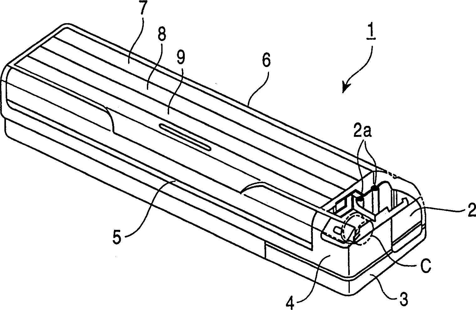
[0037] The present invention will be described based on examples. Such as figure 1 As shown in the figure as a whole, the shell of this wall-mounted indoor heat exchanger device 1 is composed of a back box 3 installed on the indoor wall through a prescribed locking member, and a cover that is used as a decorative cover on the front side of the back box 3 is covered. The case 4 and the front panel 6 attached to the front (front) of the case 4 are constituted by three members.

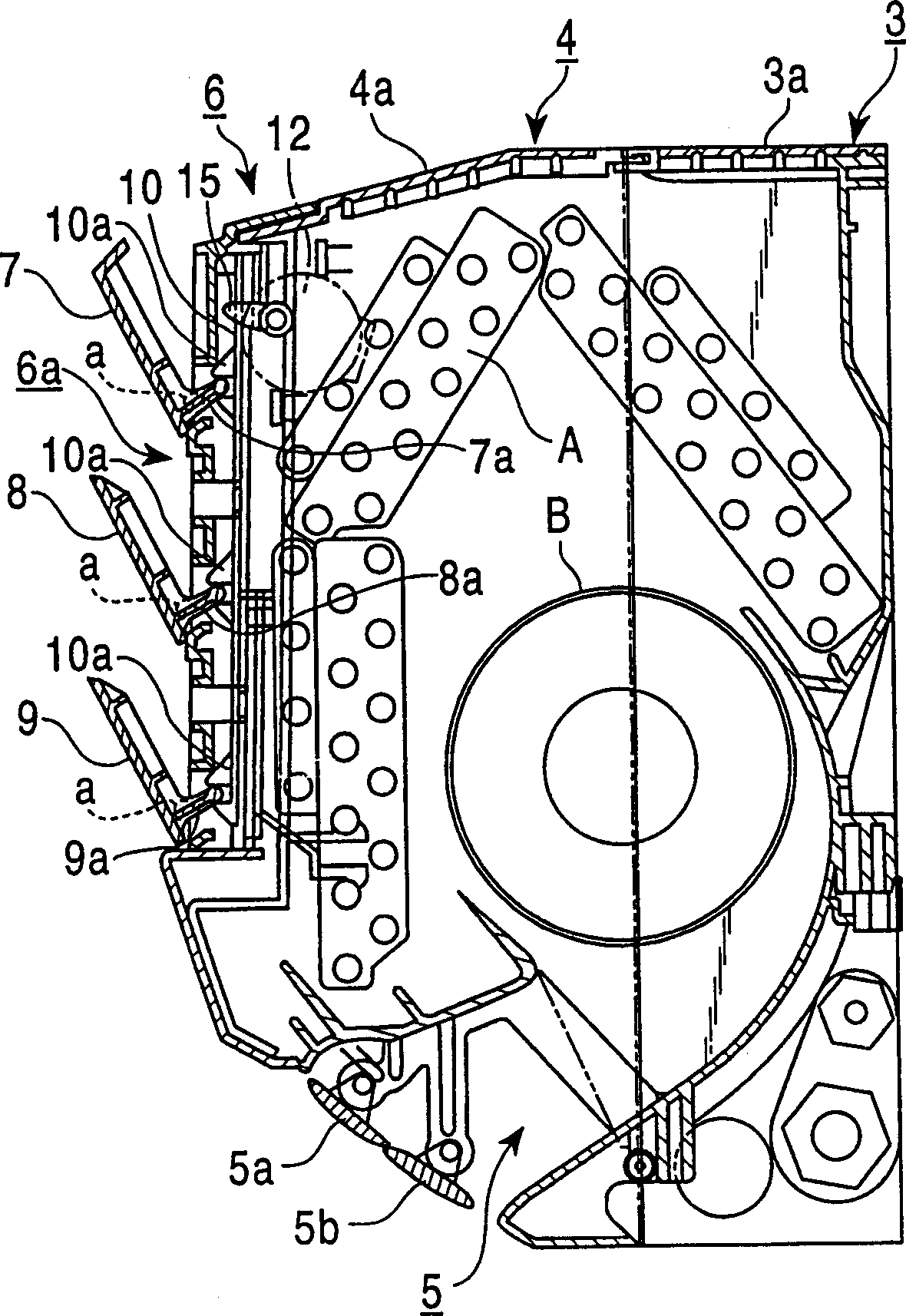
[0038] refer to figure 2 In the cross-sectional view of the back box 3, a heat exchanger A and a blower fan B as main components are stored in the back box 3, and a fan motor C and an electrical part storage part 2 for driving the blower fan are arranged on the side thereof. Furthermore, a rear top surface air suction port 3 a is formed on the top surface of the back box 3 .

[0039] The case 4 is provided with a front ceiling air suction port 4a communicating with the rear ceiling air suction port ...


PUM


Abstract

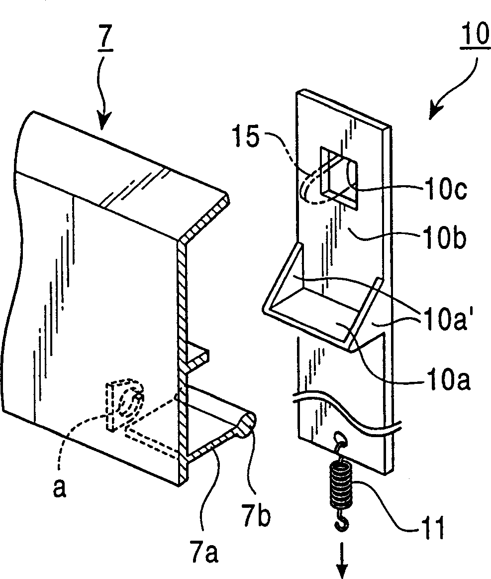
On opening and closing the louvers, provided at the air suction port in the front panel of the interior-side heat exchange unit, an arm is provided on the side of the rear surface of each of the louvers, and each of those arms is collectively driven by an interlocking plate which is reciprocatively moved linearly through the driving lever by a motor, whereby each louver is accurately interlocked to reliably open and close without the aid of the gear mechanism of pinion-rack.

Description

technical field [0001] The present invention relates to an air conditioner having an outdoor heat exchanger device (outdoor unit) and an indoor heat exchanger device (indoor unit). An air conditioner in which the suction port is opened and closed by a louver. Background technique [0002] In the case of a wall-mounted indoor heat exchanger device, almost all of the front (front) side of the housing is provided with an air suction port, and an air discharge port for blowing out heat-exchanged air is provided below it. [0003] The air outlet is provided with a wind direction plate for changing the blown air wind direction, and the air outlet is closed by the wind direction plate when the operation stops. This is to prevent dirt from entering the air discharge port when the operation is stopped, and to improve the cleanliness of the appearance by covering the inside of the air discharge port. [0004] For the same purpose, a louver is also provided on the air intake port, an...

Claims


Application Information

Patent Timeline
Patent Type & Authority Patents(China)
IPC IPC(8): F24F1/0057F24F13/14F24F13/15F24F13/20
CPCF24F2001/0048F24F13/1426F24F1/0007F24F1/0057F24F1/00
Inventor 细川佳秀杉山慎治
Owner FUJITSU GENERAL LTD
Learn More