Positioning device

a positioning device and positioning element technology, applied in the field of positioning devices, can solve the problems of inability to establish a direct correlation between the voltage applied and the expansion of the piezoelectric actuator, time-consuming and costly, and the actual position of the positioning element cannot be determined exactly, so as to achieve precise positioning of the positioning element, cost saving, and precise metering of the injected fluid

Inactive Publication Date: 2013-09-19
ROBERT BOSCH GMBH
View PDF3 Cites 1 Cited by
  • Summary
  • Abstract
  • Description
  • Claims
  • Application Information

AI Technical Summary

Benefits of technology

[0004]The positioning device according to the present invention has the advantage over the related art that in its operation two piezoelectric actuators connected in series are used, which make possible a precise positioning of the positioning element at any point in time of the injection process and thus a more precise metering of the injected fluid. This is achieved according to the present invention by the fact that the positioning device includes a positioning element, which is situated movably in a first direction and a second direction, the first and second directions being opposed to one another. Furthermore the positioning device includes a first piezoelectric actuator and a second piezoelectric actuator, the first piezoelectric actuator moving the positioning element in the first direction, and the second piezoelectric actuator moving the positioning element in the second direction. The manufacturing steps for the measuring and coding of the piezoelectric actuators may thus be omitted, which results in considerable cost savings and markedly shorter manufacturing times.
[0005]According to a preferred exemplary embodiment of the present invention, the first piezoelectric actuator moves the positioning element from a starting position into a setting position in the first direction and the second piezoelectric actuator moves the positioning element from the setting position back into the starting position in the second direction. This brings about a reliable opening and closing of the positioning element, with high dynamics.
[0006]It is also preferred that the positioning device includes a control unit, which is connected to the first and the second piezoelectric actuators. The control unit is designed to activate or trigger the first and second piezoelectric actuators alternately and also to detect the signals of the deactivated or not triggered piezoelectric actuator. In this process, the deactivated piezoelectric actuator is used as a sensor and detects the force exerted on it by the activated piezoelectric actuator as a signal which may be used to determine the position of the positioning element. This information makes it possible to determine the precise expansion of the first piezoelectric actuator and thus also the lifting movement of the positioning element. Complex measuring to select the piezoelectric actuators to be used may thus be omitted from the manufacturing stage.

Problems solved by technology

A particular disadvantage of such devices is that as a result of the characteristic degradation of the piezoelectric actuators as a function of the number of electric cycles, it is not possible to establish a direct correlation between the voltage applied and the expansion of the piezoelectric actuator.
This means that the actual position of the positioning element cannot be determined exactly at any point in time of the injection process.
In addition, every individual piezoelectric actuator has to be measured and coded in the manufacturing process, which is time-consuming and costly, in order to ascertain the individual lifting capacity for metering the fluid.
The manufacturing steps for the measuring and coding of the piezoelectric actuators may thus be omitted, which results in considerable cost savings and markedly shorter manufacturing times.
In addition, by balancing the detected fluid quantity actually injected and the setpoint quantity defined by the control unit it is possible to make a tuning, for example by inserting a further control unit which alters the setpoint quantity, significantly more difficult.
Direct operation of the positioning element allows components to be omitted, minimizing the number of components and resulting in considerable cost savings.

Method used


Image

  • Positioning device
  • Positioning device
  • Positioning device

Examples


Embodiment Construction

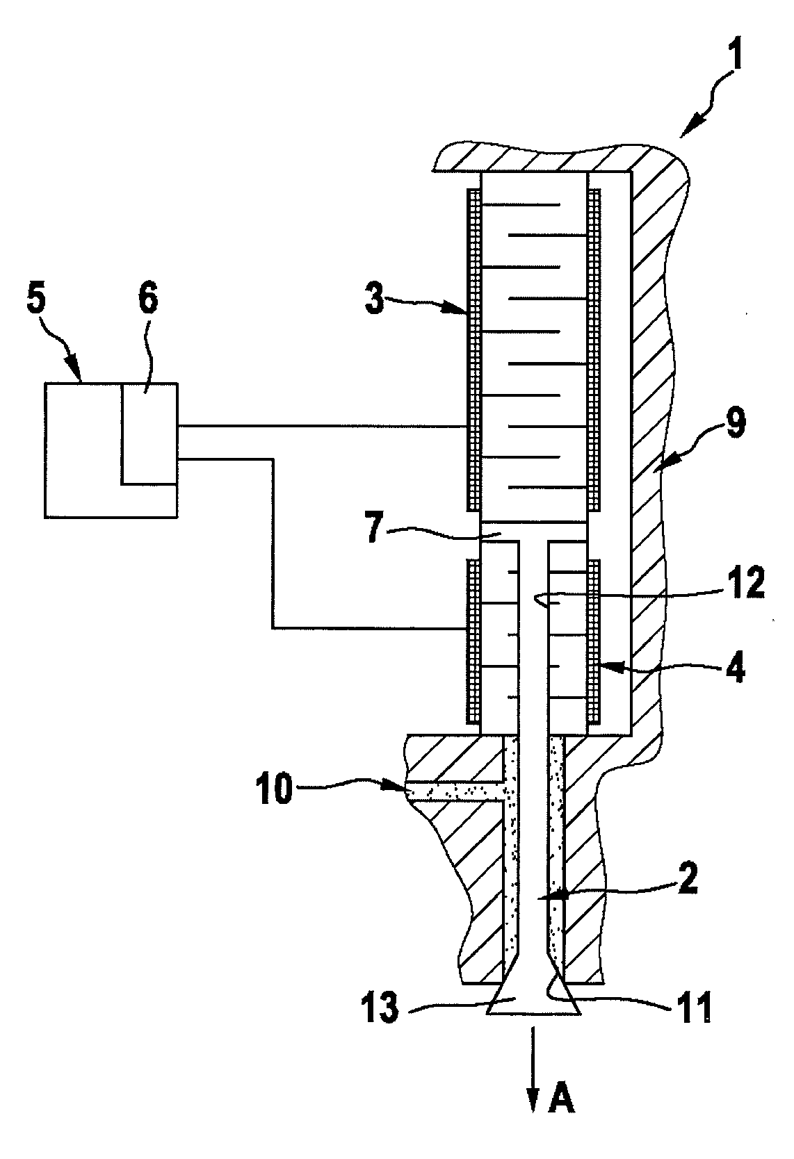
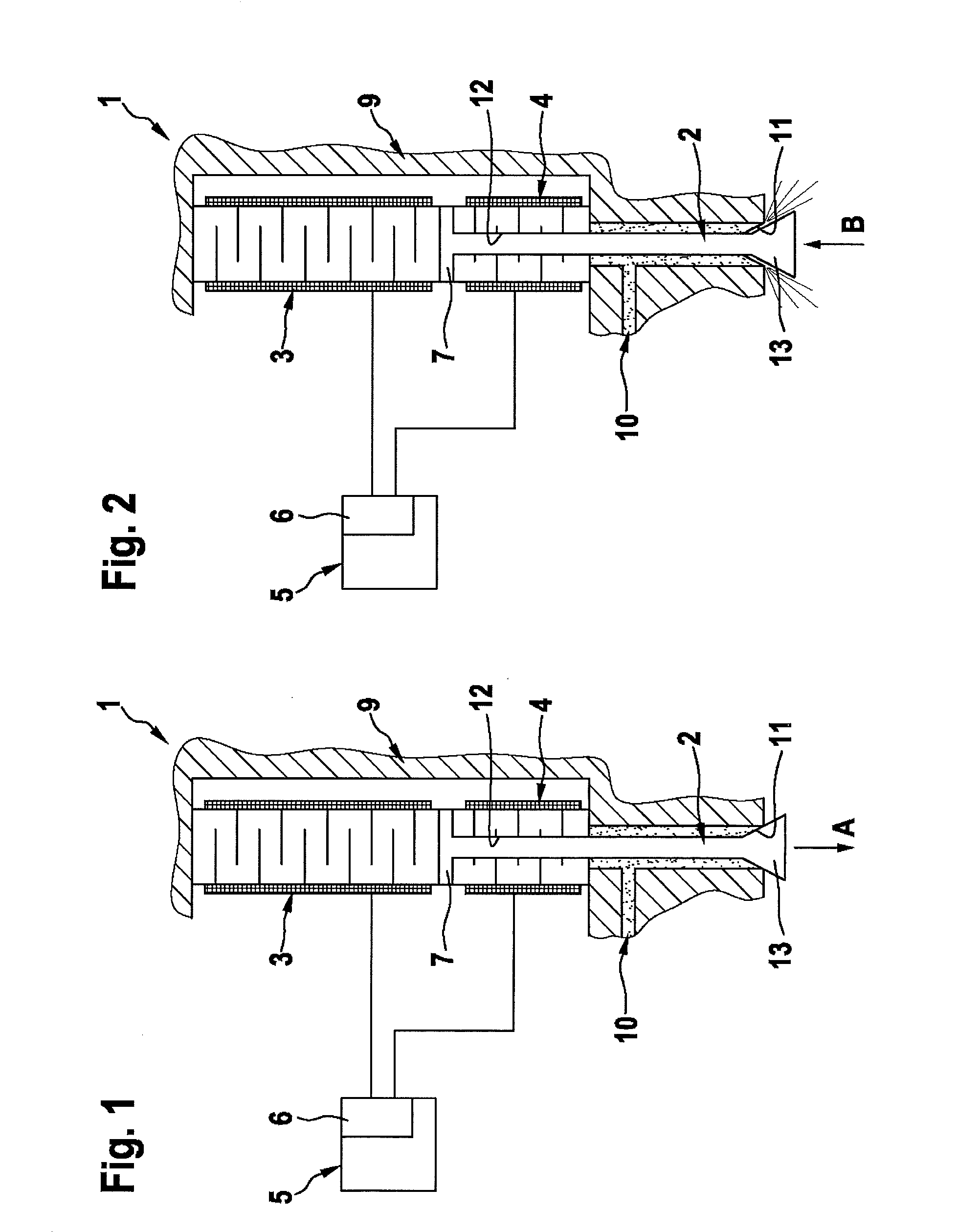
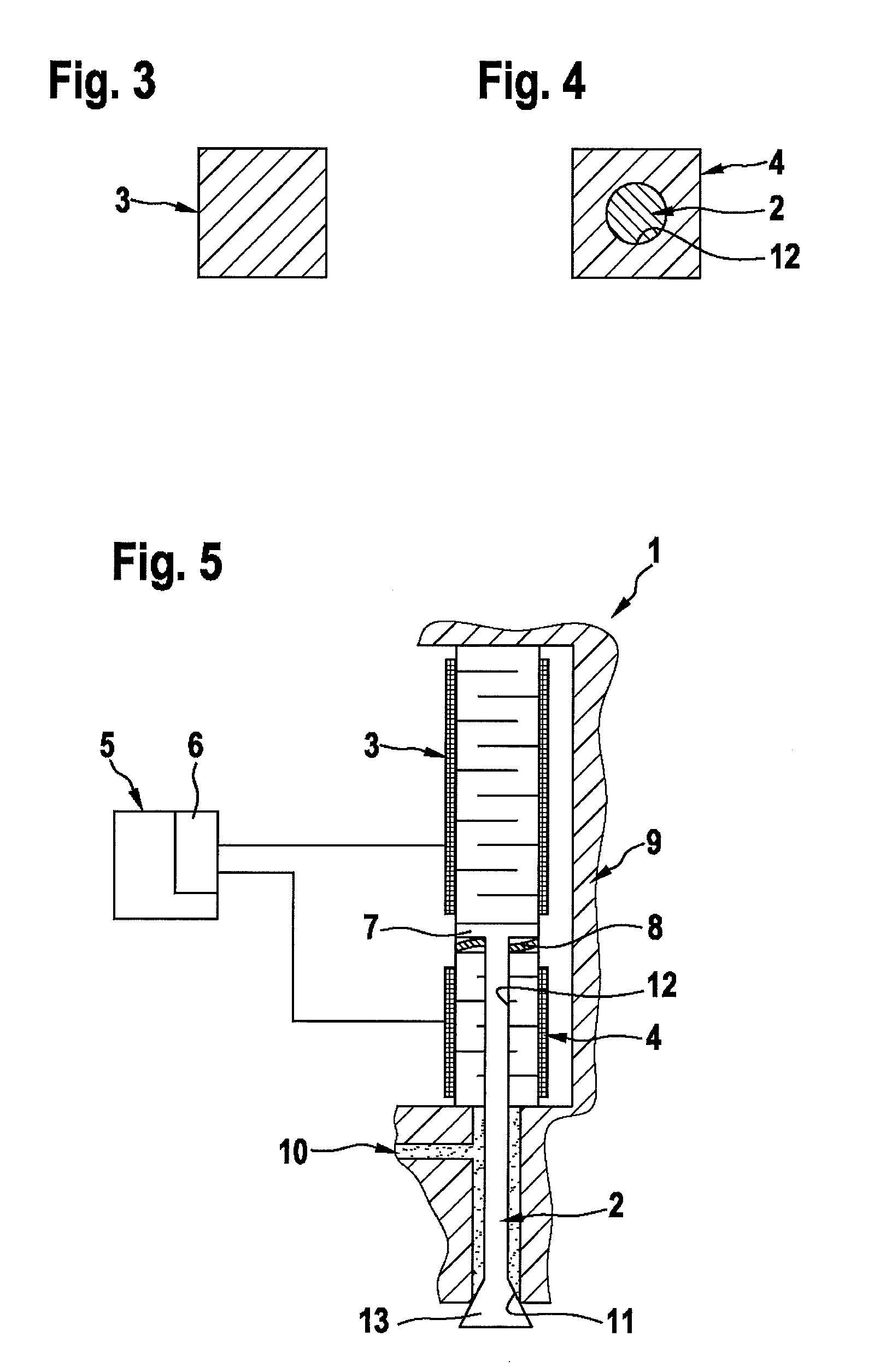
[0020]In the following, a positioning device according to a first preferred exemplary embodiment of the present invention is described in greater detail, with reference to FIGS. 1 through 4.

[0021]FIG. 1 shows a partial sectional view of a positioning device 1 according to the first exemplary embodiment of the present invention. Positioning device 1 includes a positioning element 2, a first piezoelectric actuator 3 and a second piezoelectric actuator 4, which are preferably designed as ceramic multilayer piezoelectric actuators and are situated in a housing 9, to which a fluid is supplied via a fuel line 10. In addition, positioning device 1 includes a control unit 5, situated outside housing 9, and an arithmetic unit 6 provided therein which is electrically connected to first piezoelectric actuator 3 and second piezoelectric actuator 4. First and second piezoelectric actuators 3, 4 each have a square cross section, as shown in FIGS. 3 and 4. Alternatively the piezoelectric actuators...


PUM


Abstract

A positioning device includes a positioning element that is situated movably in a first direction and a second direction, the first and the second directions being opposed to one another, and a first piezoelectric actuator and a second piezoelectric actuator, the first piezoelectric actuator moving the positioning element in the first direction and the second piezoelectric actuator moving the positioning element in the second direction.

Description

CROSS REFERENCE TO RELATED APPLICATIONS[0001]The present application is the national stage entry of International Patent Application No. PCT / EP2011 / 068656, filed on Oct. 25, 2011.FIELD OF INVENTION[0002]The present invention relates to a positioning device.BACKGROUND INFORMATION[0003]Positioning devices for purposes of fluid injection are known from the related art, in varying embodiments having needle-shaped positioning elements, which are operated with the aid of a ceramic piezoelectric actuator in order to perform rapid injections of fluid. A particular disadvantage of such devices is that as a result of the characteristic degradation of the piezoelectric actuators as a function of the number of electric cycles, it is not possible to establish a direct correlation between the voltage applied and the expansion of the piezoelectric actuator. This means that the actual position of the positioning element cannot be determined exactly at any point in time of the injection process. In ...

Claims


Application Information

Patent Timeline
Patent Type & Authority Applications(United States)
IPC IPC(8): H01L41/09H01L41/04
CPCH01L41/042H01L41/09F02M51/0603F02M61/08H02N2/02H02N2/06F02M63/0063H01L41/0835H10N30/505H10N30/20H10N30/802
Inventor WUERFEL, GERNOTPIETSCH, INGOKERKAMM, INGOSEBASTIAN, THOMASJAKOBI, ANDREAS
Owner ROBERT BOSCH GMBH
Why Eureka
Try Eureka