Cooling control structure

A technology of cooling control and channel control, applied in the direction of valve casing structure, manufacturing tools, abrasive surface adjustment devices, etc., can solve the problems that cannot meet the cooling requirements of CNC lathes

Pending Publication Date: 2022-07-01
佛山市南海和信福莱克思金属制品有限公司
View PDF0 Cites 0 Cited by
  • Summary
  • Abstract
  • Description
  • Claims
  • Application Information

AI Technical Summary

Problems solved by technology

[0002] Ordinary high-pressure pumps combined with overflow valves can only provide a constant pressure, which cannot

Method used


Image

  • Cooling control structure
  • Cooling control structure
  • Cooling control structure

Examples


Embodiment Construction

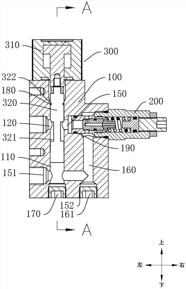
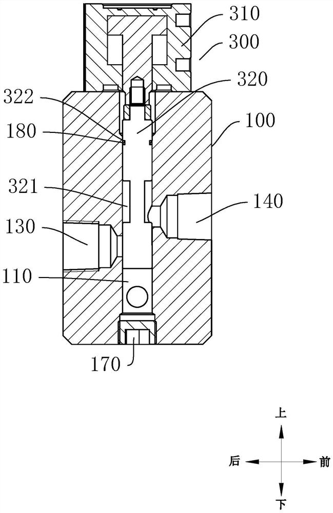
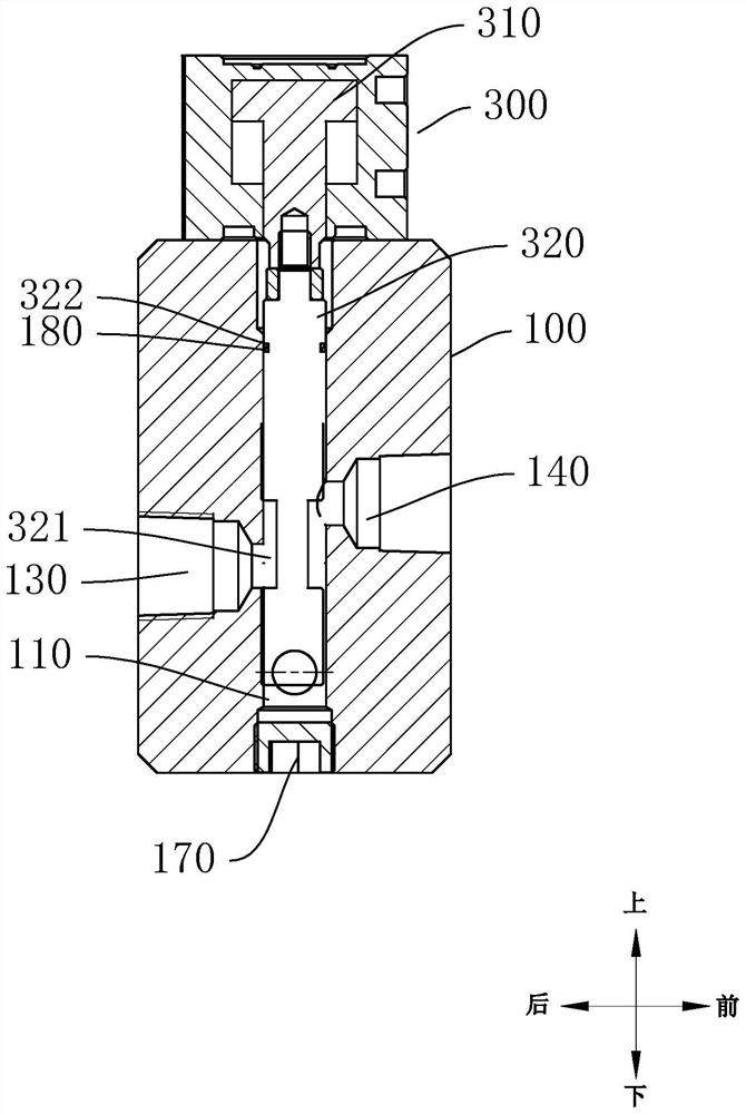
[0027] This part will describe the specific embodiments of the present invention in detail, and the preferred embodiments of the present invention are shown in the accompanying drawings. Each technical feature and overall technical solution of the invention should not be construed as limiting the protection scope of the invention.

[0028] In the description of the present invention, it should be understood that the azimuth description, such as the azimuth or position relationship indicated by up, down, front, rear, left, right, etc., is based on the azimuth or position relationship shown in the drawings, only In order to facilitate the description of the present invention and simplify the description, it is not indicated or implied that the indicated device or element must have a particular orientation, be constructed and operated in a particular orientation, and therefore should not be construed as limiting the present invention.

[0029] In the description of the present in...


PUM


Abstract

The cooling control structure comprises a shell and a control assembly, the shell is provided with a control channel extending up and down, the two ends of the control channel are the open end and the closed end respectively, the side wall of the control channel is provided with a low-pressure water outlet, a high-pressure water outlet, a high-pressure water inlet and an overflow mounting opening, and the overflow mounting opening is provided with an overflow valve; the control assembly comprises a valve element, the valve element is movably arranged in the control channel relative to the shell, the valve element is provided with a water passing structure, the valve element has three state positions in the control channel, and the three state positions comprise the first state position, the second state position and the third state position. The cooling control structure can be in three different states, namely a high-pressure water outlet state, a low-pressure water outlet state and a closed state.

Description


Claims


Application Information

Patent Timeline
Owner 佛山市南海和信福莱克思金属制品有限公司
Why Eureka
Try Eureka