Intelligent sandbag of real-time data display device

A technology of display device and real-time data, applied in the field of boxing sandbags, can solve the problem that boxing practice data cannot be effectively monitored, and achieve the effect of convenient later query and intuitive detection structure.

Pending Publication Date: 2022-07-05
苏州菠萝健康科技有限公司
11 Cites 0 Cited by

AI-Extracted Technical Summary

Problems solved by technology

[0005] Aiming at the deficiencies of the prior art, the present invention provides an intelligent sandbag with a real-time data ...

Abstract

The invention provides an intelligent sandbag with a real-time data display device, and relates to the technical field of boxing sandbags. The intelligent sandbag comprises a balance weight connecting base, a boxing sandbag body is arranged over the balance weight connecting base, a transparent observation pipeline is fixedly connected to the center of the lower surface of the boxing sandbag body in a penetrating mode, the transparent observation pipeline is made of tempered glass materials, and the sequence of colored balls can be observed conveniently; the end, away from the boxing sandbag body, of the transparent observation pipeline is fixedly connected with the center of the upper surface of the balance weight connecting base in a penetrating mode, a boxing data collecting device is arranged in the boxing sandbag body, the boxing sequence and strength are collected through the boxing data collecting device, and the result of boxing exercise is conveniently known; and the boxing data acquisition device comprises a plurality of fixed-point boxing blocks. When the sandbag is used for boxing contact, the boxing strength and the boxing sequence can be effectively monitored, the detection result is displayed in real time, and the monitoring data is uploaded to a mobile phone to be stored, so that later query is facilitated, and the practice condition is analyzed.

Application Domain

Technology Topic

Image

  • Intelligent sandbag of real-time data display device
  • Intelligent sandbag of real-time data display device
  • Intelligent sandbag of real-time data display device

Examples

  • Experimental program(1)

Example Embodiment

[0026] Example 1:
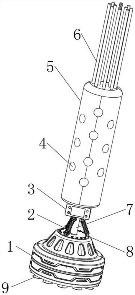
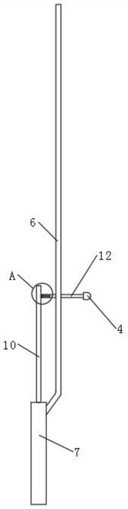
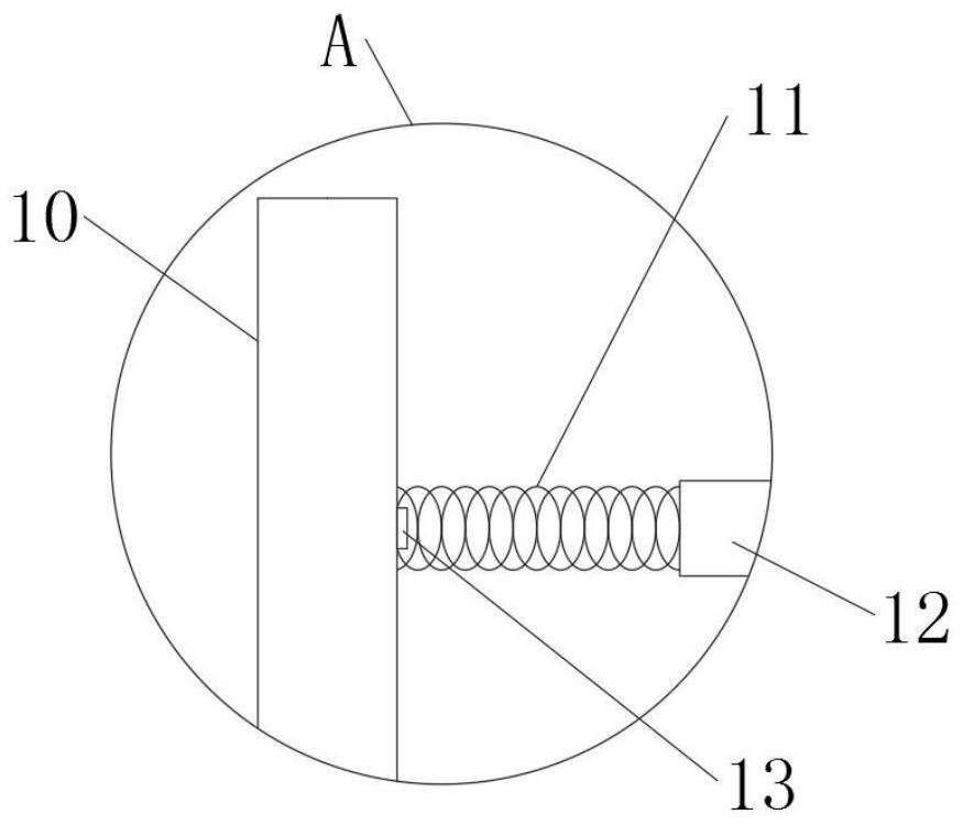
[0027] like figure 1 , figure 2 and image 3 As shown, the embodiment of the present invention provides a smart sandbag of a real-time data display device, including a counterweight connection base 1, a punching punching bag body 5 is arranged directly above the counterweight connection base 1, and a transparent punching bag body 5 is fixedly connected through the center of the lower surface of the punching punching punching bag body 5. The observation pipe 7, one end of the transparent observation pipe 7 away from the punching bag main body 5 is connected to the center of the upper surface of the counterweight connection base 1 through and fixedly connected, the punching punching bag main body 5 is provided with a punching data acquisition device, and the punching data acquisition device includes several fixed-point punching blocks 4 , and several fixed-point punching blocks 4 are connected to the outer wall of the punching bag main body 5 through sliding connection.
[0028] The upper surface of the punching bag main body 5 is fixedly connected with a number of uniformly distributed color ball storage pipes 6, and a number of color ball storage pipes 6 are located above the blocking connection block 12. Several sequential detection balls are arranged, and different color ball storage pipes 6 The colors of the color balls are different in sequence. The side wall of the colored ball storage pipe 6 is slidably connected with a blocking connection block 12, and the blocking connection block 12 is fixedly connected with a compression return spring 11 near one end of the support connection block 10.
[0029] One end of the compression return spring 11 away from the color ball storage pipe 6 is fixedly connected to the side wall of the support connection block 10, and one end of the block connection block 12 away from the support connection block 10 is fixedly connected to the inside of the fixed-point punching block 4, and the middle of the upper surface of the block connection block 12 is located in the color A ball dropping device is provided through the ball storage pipe 6 at a position away from the support connection block 10 .
[0030] The transparent observation pipe 7 is located in the center of one end of the punching sandbag body 5 and is fixedly connected with a support connection block 10, the lower surface of the counterweight connection base 1 is fixedly connected with a number of evenly distributed ground suction discs 9, and the upper surface of the counterweight connection base 1 is fixedly connected. A number of buffer connection seats 8 are fixedly connected to the lower surface of the punching sandbag body 5 , and a buffer spring 2 is fixedly connected between the buffer connection seats 8 between the punching sandbag body 5 and the counterweight connection base 1 .
[0031] like Figure 4 As shown, the outer wall of the support connection block 10 is located at the corresponding position of the compression return spring 11 and is fixedly connected with a boxing contact 13, the boxing contact 13 is connected with the sequence recorder through the cable, and the sequence recorder is respectively connected with the punching data display screen 3 and the punching data display screen through the cable. The recording result uploading module is connected, the sequence recorder is a data processor, and the boxing contact 13 is a pressure sensor.
[0032] The position of the inner wall of the punching bag body 5 is provided with a sequence recorder, and the punching contact 13 at the position of each compression return spring 11 is numbered, and the number is unique. The inner wall position of the punching punching bag body 5 is provided with a recording result uploading module, and the recording result uploading module It is a Bluetooth data transmission module, and a boxing data display screen 3 is fixedly connected to the lower surface of the punching bag body 5 .
[0033]Working principle: By hitting the fixed-point punching block 4 at the corresponding position, when it hits the fixed-point punching block 4 position, the connecting block 12 is blocked and slides, so that the ball falling device blocking the position of the connecting block 12 is aligned with the inner side of the color ball storage pipe 6, so that The sequence detection ball slips into the transparent observation pipe 6, which is convenient to directly observe whether the hitting sequence is correct. When hitting the corresponding fixed-point punching block 4, the punching contact 13 is impacted, and the punching contact 13 is recorded by the sequence recorder. Sequence and attack pressure, and display the data on the boxing data display screen 3. At the same time, the data is uploaded to the mobile phone for storage through the recording result uploading module, which is convenient for later query, and the counterweight can be effectively transferred through the ground suction plate 9. The connection base 1 is sucked and fixed on the ground, and the counterweight is connected to the base 1 to increase the counterweight, which can effectively prevent the punching bag body 5 from being knocked down. and the main body 5 of the punching sandbag is dumped, and at the same time, the main body 5 of the punching sandbag is prevented from being seriously inclined, and the transparent observation pipe 7 is effectively protected and the transparent observation pipe 7 is prevented from being damaged.

PUM

no PUM

Description & Claims & Application Information

We can also present the details of the Description, Claims and Application information to help users get a comprehensive understanding of the technical details of the patent, such as background art, summary of invention, brief description of drawings, description of embodiments, and other original content. On the other hand, users can also determine the specific scope of protection of the technology through the list of claims; as well as understand the changes in the life cycle of the technology with the presentation of the patent timeline. Login to view more.

Similar technology patents

Vehicle detection device

Owner:江苏艾倍科科技股份有限公司

Classification and recommendation of technical efficacy words

  • Easy to query later
Why Eureka
Try Eureka