Machine gun frame for combat helicopter

A technology for helicopters and machine guns, applied in aircraft parts, military equipment configuration, transportation and packaging, etc., can solve problems such as the failure of the machine gun frame lifting adjustment mechanism to work normally and the lack of shock resistance.

Active Publication Date: 2022-07-08
北京天创凯睿科技有限公司
View PDF7 Cites 0 Cited by
  • Summary
  • Abstract
  • Description
  • Claims
  • Application Information

AI Technical Summary

Problems solved by technology

[0003] The present invention aims to provide a machine gun mount for combat helicopters to solve the problem that the anti-vibration capability of comb

Method used


Image

  • Machine gun frame for combat helicopter
  • Machine gun frame for combat helicopter
  • Machine gun frame for combat helicopter

Examples


Embodiment 1

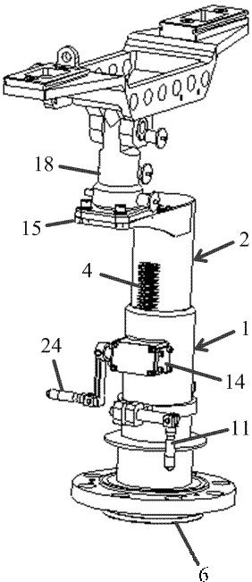
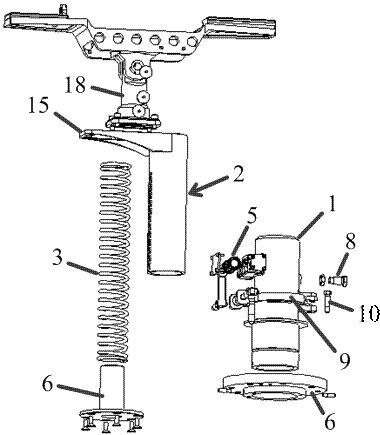
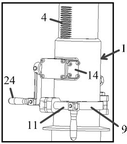
[0052] A machine gun mount for combat helicopters, such as figure 1 and figure 2 shown, it includes:

[0053] A sleeve assembly, including: an inner sleeve 1 and an outer sleeve 2 that are sleeved and connected in a sliding manner and used to adjust the height of the machine gun frame;

[0054] The sleeve driver 3 applies pressure to the inner sleeve 1 and the outer sleeve 2 to keep the two away from each other, thereby raising the machine gun frame; such as figure 2 As shown, the sleeve driving member 3 is a compression spring, which is arranged in the cavity enclosed by the inner sleeve 1 and the outer sleeve 2; the upper end of the compression spring is connected to the inner cavity of the inner sleeve 1 The top surfaces are connected to push the inner sleeve 1 away from the outer sleeve 2 . In addition, the above-mentioned sleeve assembly further includes: a buffer spring base 6, which is provided with a cylindrical boss, and the compression spring is sleeved on the c...


PUM


Abstract

A machine gun frame for a combat helicopter comprises a sleeve assembly which comprises an inner sleeve and an outer sleeve which are connected in a sleeved and sliding mode and used for adjusting the height of the machine gun frame; the sleeve driving part is used for applying pressure to the inner sleeve and the outer sleeve to enable the inner sleeve and the outer sleeve to be far away from each other, so that the machine gun rack is lifted; a limiting clamping groove is formed in the outer circumferential wall of the inner sleeve, and the limiting gear assembly is arranged on the outer sleeve and comprises a limiting gear connected with the limiting clamping groove in a matched and clamped mode; the limiting gear and the limiting clamping groove which are connected in a matched and clamped mode are used for limiting the inner sleeve and the outer sleeve to be away from each other. Through the sleeve driving part and the limiting gear assembly, the problem that a lifting adjusting mechanism of a machine gun frame cannot work normally due to the fact that a combat helicopter in the prior art is insufficient in shock resistance can be effectively solved.

Description

technical field [0001] The invention relates to the technical field of combat helicopter shooting accessories, in particular to a machine gun mount for combat helicopters. Background technique [0002] Combat helicopters require machine guns to be installed at the hatch so that the helicopter can fire during flight. However, due to the fact that combat helicopters often do some relatively large evasion and pursuit movements during the flight, and the machine gun will also produce large vibrations during the shooting process. This requires that the machine gun mount on the combat helicopter has a strong anti-vibration capability and can adapt to the special requirements of the combat helicopter. However, the existing machine gun mounts often use a gear structure that meshes with each other to drive the machine gun mount to move up and down, thereby completing the height adjustment of the machine gun mount. However, when the above-mentioned gear structure is impacted or the ...

Claims


Application Information

Patent Timeline
IPC IPC(8): B64D7/06
CPCB64D7/06
Inventor 王文良崔明宝宋述稳
Owner 北京天创凯睿科技有限公司
Why Eureka
Try Eureka