Discharge device of stuffed food forming machine

A discharge device and molding machine technology, applied in the direction of manipulators, food science, dough processing, etc., can solve the problems of simple function, complex structure, no further improvement of the discharge device of stuffed food, etc., to achieve stable movement, Strong clamping effect

Active Publication Date: 2018-09-21
CHENGDU SOONTRUE MECHANICAL EQUIP CO LTD
View PDF2 Cites 0 Cited by
  • Summary
  • Abstract
  • Description
  • Claims
  • Application Information

AI Technical Summary

Problems solved by technology

[0005] To sum up, in the prior art, there is no further improvement on the discharging device for the stuffed food, resulting in the existing discharging device having a complex structure or simple function, and unable to stably perform the clamping operation on the stuffed food

Method used


Image

  • Discharge device of stuffed food forming machine
  • Discharge device of stuffed food forming machine

Examples


Embodiment 1

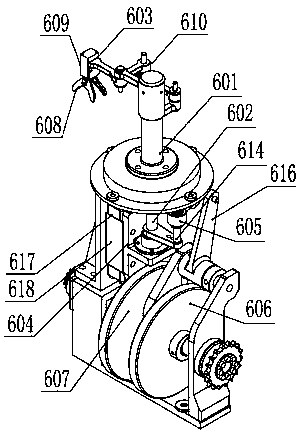
[0030] The discharge device of the stuffed food forming machine includes a rotating seat 601, the middle part of which is connected with a lifting rotating shaft 602, and the top of the rotating seat 601 is provided with a finger chuck 603, and the lifting rotating shaft 602 is connected with the lifting shaft 604 through the mounting seat 604. The sliding block 618 is connected, and the lifting shaft 602 is also sleeved with a sliding sleeve 605 , the sliding sleeve 605 is connected with the swing cam 606 , and the mounting base 604 is connected with the lifting cam 607 . The finger chuck 603 includes a pair of clamping blocks 608 and a finger cylinder 609 for driving the clamping blocks 608 to move.

[0031] The overall movement of the application is stable, the clamping is firm, and the food will not fall or the like.

Embodiment 2

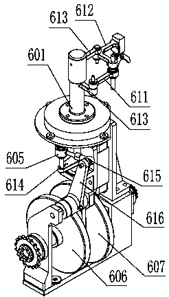
[0033] The discharge device of the stuffed food forming machine includes a rotating seat 601, the middle part of which is connected with a lifting rotating shaft 602, and the top of the rotating seat 601 is provided with a finger chuck 603, and the lifting rotating shaft 602 is connected with the lifting shaft 604 through the mounting seat 604. The sliding block 618 is connected, and the lifting shaft 602 is also sleeved with a sliding sleeve 605 , the sliding sleeve 605 is connected with the swing cam 606 , and the mounting base 604 is connected with the lifting cam 607 . The finger chuck 603 includes a pair of clamping blocks 608 and a finger cylinder 609 for driving the clamping blocks 608 to move. The finger chuck 603 is connected to the rotating seat 601 through a parallel swing link 610, and the parallel swing link 610 includes at least one connecting rod. The parallel swing link 610 includes a connecting rod A611 and a connecting rod B612, the connecting rod B612 is L-s...


PUM


Abstract

The invention belongs to the technical field of food processing and particularly relates to a discharging device of a stuffed-food forming machine. The discharging device comprises a rotary seat, wherein a lifting rotary shaft is connected to the middle part of the rotary seat; a finger chuck is arranged at the top part of the rotary seat; the lifting rotary shaft is connected with a lifting sliding block by an installing seat; a sliding sleeve is also sheathed and connected with the lifting rotary shaft and is connected with a swinging cam; the installing seat is connected with the lifting cam. A swinging arm of the swinging cam can finish swinging under the action of the swinging cam, the lifting rotary shaft can realize both rotation and the lifting action simultaneously under the action of the swinging cam and the lifting cam, so that stuffed food is clamped and lifted from a mold cup, is transferred in a rotating manner and is placed on a conveying belt. The discharging device has the advantages that the whole movement is stable, the clamping is firm and the conditions such as food falling and the like can be avoided.

Description

technical field [0001] The invention belongs to the technical field of food processing, in particular to a discharge device of a stuffed food forming machine. Background technique [0002] The existing food forming machines for processing dumpling-like stuffed foods usually have a relatively large volume when the food is formed and processed. Although the production efficiency is very high, due to the problem of volume, the application of the stuffed food forming machine The places are limited to large workshops or factories, but due to the increasing labor costs in the catering industry, the demand for purchasing food automation production equipment has also increased significantly. It is too large to be directly applied in ordinary restaurants, and its cost is also very high. However, the small food forming machines in the prior art are too low in automation and work efficiency is not high. The structure of the discharge device is either too complicated, or the structure ...

Claims


Application Information

Patent Timeline
Patent Type & Authority Patents(China)
IPC IPC(8): A21C9/06
CPCA21C9/08B25J11/0045
Inventor 彭涛周莉
Owner CHENGDU SOONTRUE MECHANICAL EQUIP CO LTD
Why Eureka
Try Eureka