
Lock locking device and use method

A technology of locking devices and locks, which is applied in transportation and packaging, vehicle parts, electrical components, etc., can solve the problems that locks cannot be effectively controlled, achieve reliable control, avoid safety problems, and achieve the effect of control

Active Publication Date: 2022-07-12
ZHUHAI UNITECH POWER TECH CO LTD
View PDF8 Cites 0 Cited by
  • Summary
  • Abstract
  • Description
  • Claims
  • Application Information

AI Technical Summary

Problems solved by technology

[0003] The main purpose of the present invention is to provide a lock locking device and a method of use to solve the problem that the locks on the electric power maintenance equipment in the prior art cannot be effectively controlled

Method used


Image

  • Lock locking device and use method
  • Lock locking device and use method
  • Lock locking device and use method

Examples


Embodiment Construction

[0032] It should be noted that the embodiments in the present application and the features of the embodiments may be combined with each other in the case of no conflict. The present invention will be described in detail below with reference to the accompanying drawings and in conjunction with the embodiments.

[0033] It should be noted that, unless otherwise specified, all technical and scientific terms used in this application have the same meaning as commonly understood by one of ordinary skill in the art to which this application belongs.

[0034] In the present invention, unless otherwise stated, the directional words used such as "upper, lower, top, bottom" are usually for the directions shown in the drawings, or for the components themselves in vertical, In terms of vertical or gravitational direction; similarly, for the convenience of understanding and description, "inner and outer" refers to the inner and outer relative to the contour of each component itself, but the...


PUM


Abstract

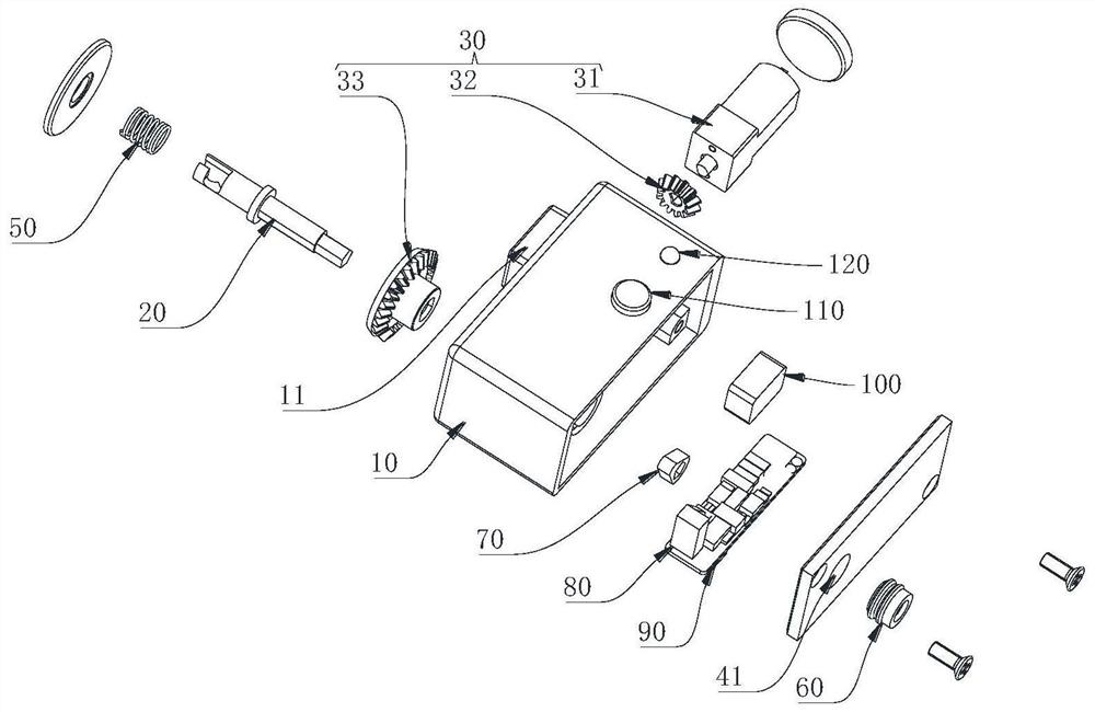
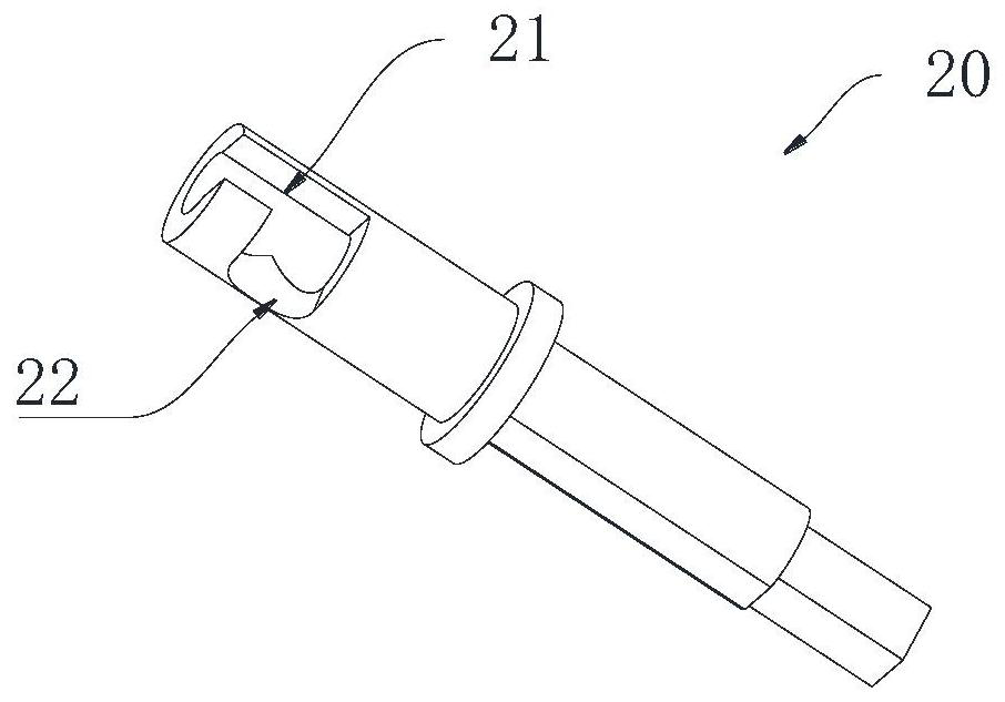
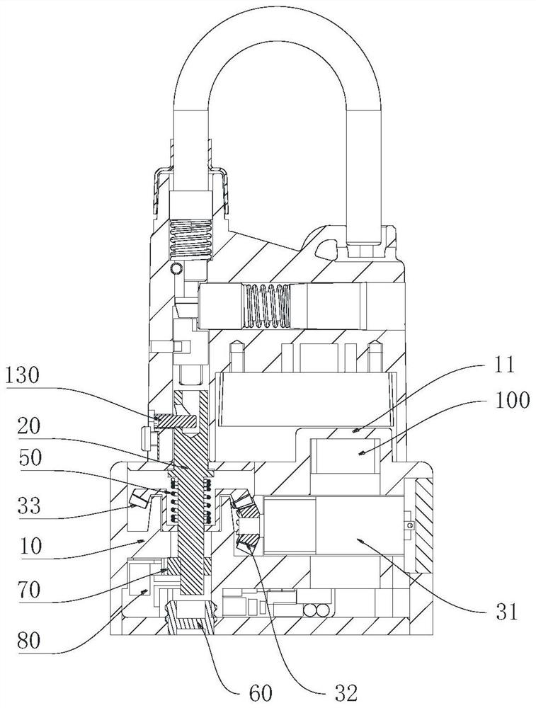
The invention provides a lockset locking device and a using method. The lockset locking device comprises a shell, the locking pin is rotatably arranged on the shell in a penetrating mode, a first sliding groove and a second sliding groove are formed in the side wall of the end, extending out of the shell, of the locking pin, the first sliding groove extends in the axial direction of the locking pin and communicates with the end face of the locking pin, and the second sliding groove extends in the circumferential direction of the locking pin and communicates with the first sliding groove; the driving assembly is in driving connection with the locking pin and drives the locking pin to rotate, when the lockset locking device is in butt joint with a lockset, the shell shields an unlocking hole of the lockset, a pin shaft on the lockset enters the first sliding groove, the driving assembly drives the locking pin to rotate and enables the pin shaft to enter the second sliding groove, and the pin shaft is in stop fit with the side wall of the second sliding groove. And the lockset is locked on the lockset locking device. The problem that in the prior art, locks on electric power overhaul equipment cannot be effectively managed and controlled is solved.

Description

technical field [0001] The present invention relates to the technical field of locks, and in particular, to a locking device for a lock and a method for using the same. Background technique [0002] At present, in the electrical maintenance work, the isolation equipment at the perimeter of the maintenance equipment has been locked and isolated with five-proof locks, but it cannot be ensured that the equipment will not be operated by personnel after unlocking the locks (unlocking keys, etc.) without authorization. Especially the temporary high-risk points (metal isolation baffles, switch cabinet doors, mesh doors), once misused, will cause serious accidents. In addition, due to the low level of intelligence, poor perception and lack of status information of ordinary five-proof locks, the real-time status information of the isolation boundary equipment, especially the isolation boundary equipment at high-risk points, cannot be effectively obtained during the maintenance period...

Claims


Application Information

Patent Timeline
Patent Type & Authority Applications(China)
IPC IPC(8): H01H9/28
CPCH01H9/281Y02T10/7072
Inventor 陈钦文褚兆勇顾裕林文琪修洪江
Owner ZHUHAI UNITECH POWER TECH CO LTD
Learn More