Double-layer conductive electrical terminal

An electrical terminal and conduction technology, which is applied in the field of electrical terminals with double-layer conduction, can solve the problems of complicated operation, multiple vacant ports, and reduce the use effect of electrical terminals with double-layer conduction, so as to improve the use effect, Quick switch effect

Inactive Publication Date: 2022-07-15
镇江多特蒙电气有限公司
View PDF0 Cites 0 Cited by
  • Summary
  • Abstract
  • Description
  • Claims
  • Application Information

AI Technical Summary

Problems solved by technology

[0003] Through practical application, it has been found that when the existing double-layer electrical terminals with conduction are installed, the conduction sheet for conduction is mostly directly welded between the conduction sheets on the upper and lower sides, and in the process of connecting the specific electrical harness In the above, not all Unicom wiring harnesses need to be shorted up and down, which leads to more vacant ports on the same double-layer electrical terminal with conduction. The difference between the terminals is the conductive sheet. The fixed conductive sheet will make the terminal only perform the function of connecting up and down, and cannot switch the state according to the demand. The use effect of the terminal; secondly, most of the existing double-layer electrical terminals with conduction are equipped with guide rails, and the double-layer electrical terminals with conduction can slide along the guide rails, mostly by sliding the terminals into the guide rail from one side of the guide rail. The problem with this combination method is that after the guide rail is fixed inside the electrical box, if there is insufficient space on both sides of the guide rail, the entire guide rail needs to be removed for subsequent maintenance and replacement of the terminals. Convenience of use with conductive electrical terminals

Method used


Image

  • Double-layer conductive electrical terminal
  • Double-layer conductive electrical terminal
  • Double-layer conductive electrical terminal

Examples


Embodiment Construction

[0030] The technical solutions in the embodiments of the present invention will be clearly and completely described below with reference to the accompanying drawings in the embodiments of the present invention. Obviously, the described embodiments are only a part of the embodiments of the present invention, rather than all the embodiments. Based on the embodiments of the present invention, all other embodiments obtained by those of ordinary skill in the art without creative efforts shall fall within the protection scope of the present invention.

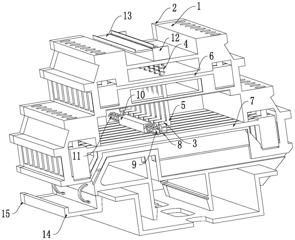
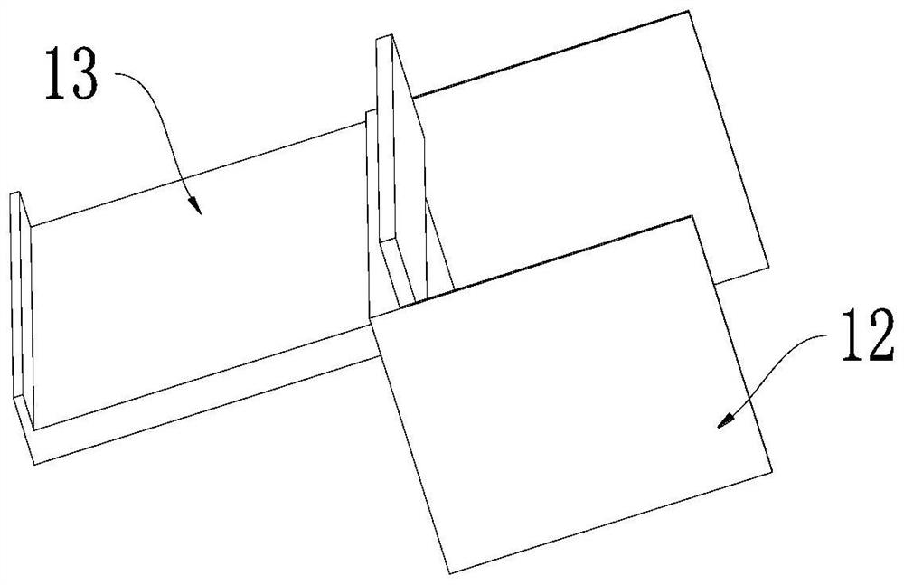
[0031] see Figure 1-7 , the present invention provides a kind of technical scheme:

[0032] A double-layer electrical terminal with conduction, comprising a shell 1 and a side plate 2 that are fixedly connected, the inner surface wall of the shell 1 is provided with two sets of terminals distributed up and down, and the two sets of terminals are respectively connected by a conducting sheet 16 Connected to the conductive sheet 2 7, ...


PUM


Abstract

The invention discloses a double-layer electrical terminal with conduction, which comprises a shell and a side plate which are fixedly connected, two groups of terminals which are distributed up and down are arranged on the inner surface wall of the shell, the two groups of terminals are respectively in conduction connection through a conduction sheet I and a conduction sheet II, and the electrical terminal further comprises multiple groups of conduction rods which are vertically arranged on the inner surface wall of the shell in a penetrating manner, the multiple groups of conducting rods are composed of insulating sections and conducting sections, and first springs are elastically connected between the outer surface walls of the conducting rods and the inner surface wall of the shell. In the application, when the subsequent conduction rod slides along the vertical end of the matching seat, the convex rod on the outer surface wall of the conduction rod goes through the process of pushing the damping fin to turn over, namely pushing the damping fin to axially rotate and expand the torsional spring, so that certain damping is provided for the subsequent conduction rod, and the situation that two groups of ports are simultaneously conducted due to too high speed is avoided; therefore, the use effect of the double-layer conductive electrical terminal is improved.

Description

technical field [0001] The present invention relates to the technical field of electrical terminals, in particular to a double-layer conductive electrical terminal. Background technique [0002] An electrical terminal is an accessory product used to achieve electrical connection, which is divided into the category of connectors in the industry. With the increasing degree of industrial automation and the stricter and more precise requirements of industrial control, the amount of terminal blocks is gradually increasing. With the development of the electronics industry, the use of terminal blocks is increasing, and there are more and more types. [0003] Through practical application, it is found that when the existing double-layer conductive electrical terminals are installed, the conductive plates for conduction are directly welded between the upper and lower conductive plates. Usually, not all connected wiring harnesses need to be shorted at the top and bottom, which leads...

Claims


Application Information

Patent Timeline
Patent Type & Authority Applications(China)
IPC IPC(8): H01R9/26H01R4/48
CPCH01R9/26H01R4/4863
Inventor 张胜豪
Owner 镇江多特蒙电气有限公司
Why Eureka
Try Eureka