Millimeter wave radar for vehicle and control method thereof

A millimeter-wave radar and vehicle technology, applied in the field of vehicle radar, can solve the problems of radar mutual interference, unfavorable cost control, high cost, etc., and achieve the effect of meeting driving needs

Pending Publication Date: 2022-07-19
HELLA SHANGHAI ELECTRONICS
View PDF0 Cites 0 Cited by
  • Summary
  • Abstract
  • Description
  • Claims
  • Application Information

AI Technical Summary

Problems solved by technology

[0003] In order to cover the front and side areas of the car, the existing automotive millimeter-wave radar system usually adopts two front-angle radars and one forward-looking radar. The two front-angle radars are respectively installed on the front corners of the vehicle to detect the side Area, the forward-looking radar is located at the front of the vehicle and is used to detect the area directly in front of the vehicle. The cost of this method is relatively high, which is not conducive to cost control in the vehicle production process
In addition, the front radar has the problem of anti-interference. The front radar is installed in front of the car, near the engine compartment. The environment it faces is very complicated, and the problem of electromagnetic interference must be solved. interference
This solution requires the use of three millimeter-wave radars, among which the forward-looking radar and the corner radar are different types of radars, and the requirements for anti-interference are higher, which increases the complexity of the system, and the radars are easy to interact with each other.

Method used


Image

  • Millimeter wave radar for vehicle and control method thereof
  • Millimeter wave radar for vehicle and control method thereof
  • Millimeter wave radar for vehicle and control method thereof

Examples


Embodiment Construction

[0046] The advantages of the present invention are further described below with reference to the accompanying drawings and specific embodiments.

[0047] Exemplary embodiments will be described in detail herein, examples of which are illustrated in the accompanying drawings. Where the following description refers to the drawings, the same numerals in different drawings refer to the same or similar elements unless otherwise indicated. The implementations described in the illustrative examples below are not intended to represent all implementations consistent with this disclosure. Rather, they are merely examples of apparatus and methods consistent with some aspects of the present disclosure as recited in the appended claims.

[0048] The terminology used in the present disclosure is for the purpose of describing particular embodiments only and is not intended to limit the present disclosure. As used in this disclosure and the appended claims, the singular forms "a," "the," an...


PUM


Abstract

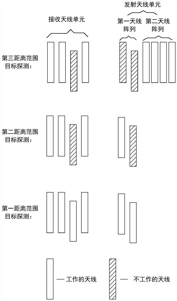
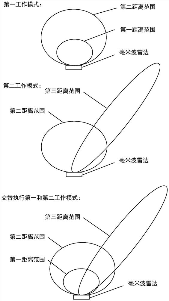
The invention provides a millimeter wave radar for a vehicle and a control method thereof, the millimeter wave radar comprises an antenna unit, an MMIC and an MCU, the antenna unit comprises a transmitting antenna unit and a receiving antenna unit, the transmitting antenna unit comprises a first antenna array for target detection in a first distance range and a second distance range and a third antenna array for target detection in a third distance range, the third distance range is larger than the second distance range, and the second distance range is larger than the first distance range; the MMIC is connected with the antenna unit and is used for modulating a signal transmitted by the transmitting antenna unit and demodulating a signal received by the receiving antenna unit; and the MCU is connected with the MMIC and is used for controlling the first antenna array and the second antenna array to work periodically. After the technical scheme is adopted, the number of radars in the existing vehicle can be reduced under the condition of realizing a good detection effect, so that the cost is reduced.

Description

technical field [0001] The present invention relates to the technical field of vehicle radar, in particular to a millimeter-wave radar for vehicles and a control method thereof. Background technique [0002] In order to meet the needs of intelligent assisted driving and unmanned driving, it is necessary to collect the external environment information of the vehicle. In the acquisition of the surrounding environment, model establishment, and obstacle detection, the millimeter wave class has played an important role, and has been widely used in scenarios such as automatic parking and adaptive cruise. With the rapid development of intelligent driving technology, millimeter-wave radar has become the main sensor in advanced driver assistance systems (ADAS) due to its long detection distance, small environmental impact, low cost, and mature technology. [0003] In order to cover the front and side areas of the car, the existing automotive millimeter-wave radar system adopts the s...

Claims


Application Information

Patent Timeline
Patent Type & Authority Applications(China)
IPC IPC(8): G01S7/02G01S13/931
CPCG01S7/02G01S13/931
Inventor 邵婉君罗沄夏敬初张磊磊
Owner HELLA SHANGHAI ELECTRONICS
Why Eureka
Try Eureka