
A point target search and detection device based on multi-line time-difference scanning extended sampling

A detection device and scanning expansion technology, applied in the field of moving target search detection devices, can solve the problems of difficulty in detecting weak and small targets, long single scanning time, elimination of unfavorable backgrounds, etc., and achieve two-dimensional expansion, easy implementation, and mature technology. Effect

Active Publication Date: 2017-04-19
CHINA ACADEMY OF SPACE TECHNOLOGY
View PDF5 Cites 0 Cited by
  • Summary
  • Abstract
  • Description
  • Claims
  • Application Information

AI Technical Summary

Problems solved by technology

In the current linear array imaging device, a single-line array detector is used, and the single scan time is long (usually ≥ 5s), and the background changes greatly between two scans, which is not conducive to background elimination. It is difficult to detect weak targets

Method used


Image

  • A point target search and detection device based on multi-line time-difference scanning extended sampling
  • A point target search and detection device based on multi-line time-difference scanning extended sampling
  • A point target search and detection device based on multi-line time-difference scanning extended sampling

Examples


Embodiment 1

[0021] Embodiment 1—Front-end scanning, multi-line time-difference scanning extended sampling detector

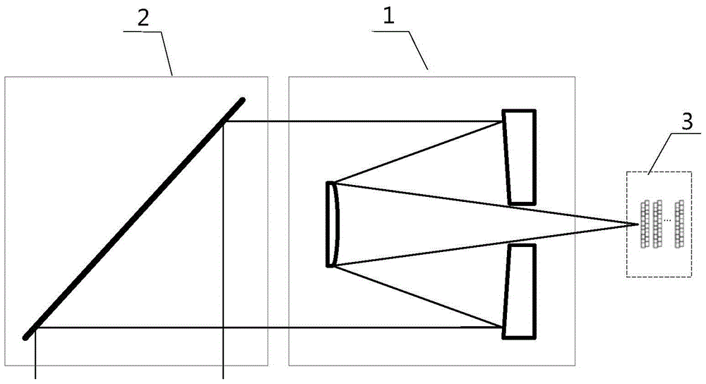
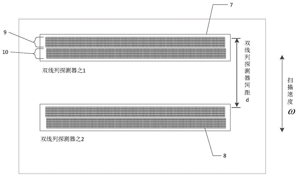
[0022] Such as figure 1 As shown, a point target search and detection device based on multi-line time-difference scanning extended sampling, the detection device works on a satellite platform, including an optical system 1, a scanning mechanism 2 and a multi-line column detector 3; the scanning mechanism It includes a swing mirror and its driving device; the scanning mechanism is located at the front end of the optical system, and the size of the swing mirror should be larger than the aperture of the optical system; the multi-line detector is a double-line detector such as image 3 7, 8 as shown in, or including N d line detectors, such as Figure 4 The numbers 11, 12, and 13 shown, each line detector is arranged in parallel, and the distance between two adjacent line detectors is d i , where i=1,2,…,N d -1,N d >2; Any two linear detectors can detect motion speed great...

Embodiment 2

[0025]Embodiment 2—Back-end scanning, multi-line time-difference scanning extended sampling detector

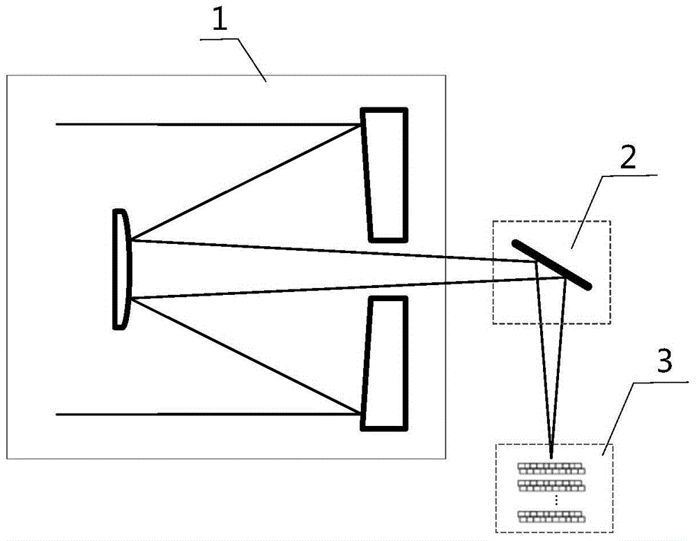
[0026] Such as figure 2 As shown, a point target search and detection device based on multi-line time-difference scanning extended sampling, the detection device works on a satellite platform, including an optical system 1, a scanning mechanism 2 and a multi-line column detector 3; the scanning mechanism 2 includes a swing mirror and its driving device; the scanning mechanism 2 is located at the rear end of the optical system 1; the linear detector is a double linear detector such as image 3 Labels 7 and 8 shown in ; two linear detectors can detect motion speed greater than v T goals, among which The scanning angular velocity ω of the scanning mechanism 2, the distance d between two linear detectors, the focal length f of the optical system, and the ground sampling distance GSD of the linear detectors. The dual line detector consists of image 3 shown.

[0027] In thi...


PUM


Abstract

A point target search and detection device based on multi-line time difference scanning extended sampling. The imaging device works on a satellite platform and includes an optical system, a scanning mechanism and a multi-line detector; the scanning mechanism includes a swing mirror and its drive Device; the multi-line detector includes Nd line detectors, each line detector is arranged in parallel, and the distance between two adjacent line detectors is di; any two line detectors can Detect targets moving at a speed greater than vT. The incident light containing the target and background radiation energy information is reflected by the pendulum mirror and converged to the focal plane by the optical system to form an image of the scene. The driving device drives the pendulum mirror to rotate at the angular rate ω to make the scene image The image sweeps through each line detector in a certain sequence. The line detector samples the image of the scene. When the image of the scene completely passes through the line detector, a complete image is formed.

Description

technical field [0001] The invention relates to a moving target search and detection device, which can be used as a space-based detection system for air / space moving targets. Background technique [0002] The key to the moving target search and detection device based on multi-line time-difference scanning is to form multiple images with a certain time interval. Using the characteristics that the background does not move in a short time and the target moves relative to the background, the background is filtered out by subtracting the time-difference images. , to achieve target detection. In the current linear array imaging device, a single-line array detector is used, and the single scan time is long (usually ≥ 5s), and the background changes greatly between two scans, which is not conducive to background elimination. It is difficult to detect weak targets. Contents of the invention [0003] The technical problem of the present invention is to overcome the deficiencies of...

Claims


Application Information

Patent Timeline
Patent Type & Authority Patents(China)
IPC IPC(8): H04N5/225H04N5/232H04N5/335H04N5/341H04N25/00
Inventor 王虎妹王世涛董小萌孙晓峰宋鹏飞刘晓磊
Owner CHINA ACADEMY OF SPACE TECHNOLOGY
Learn More