Safe overflow device of condensate water collecting tank

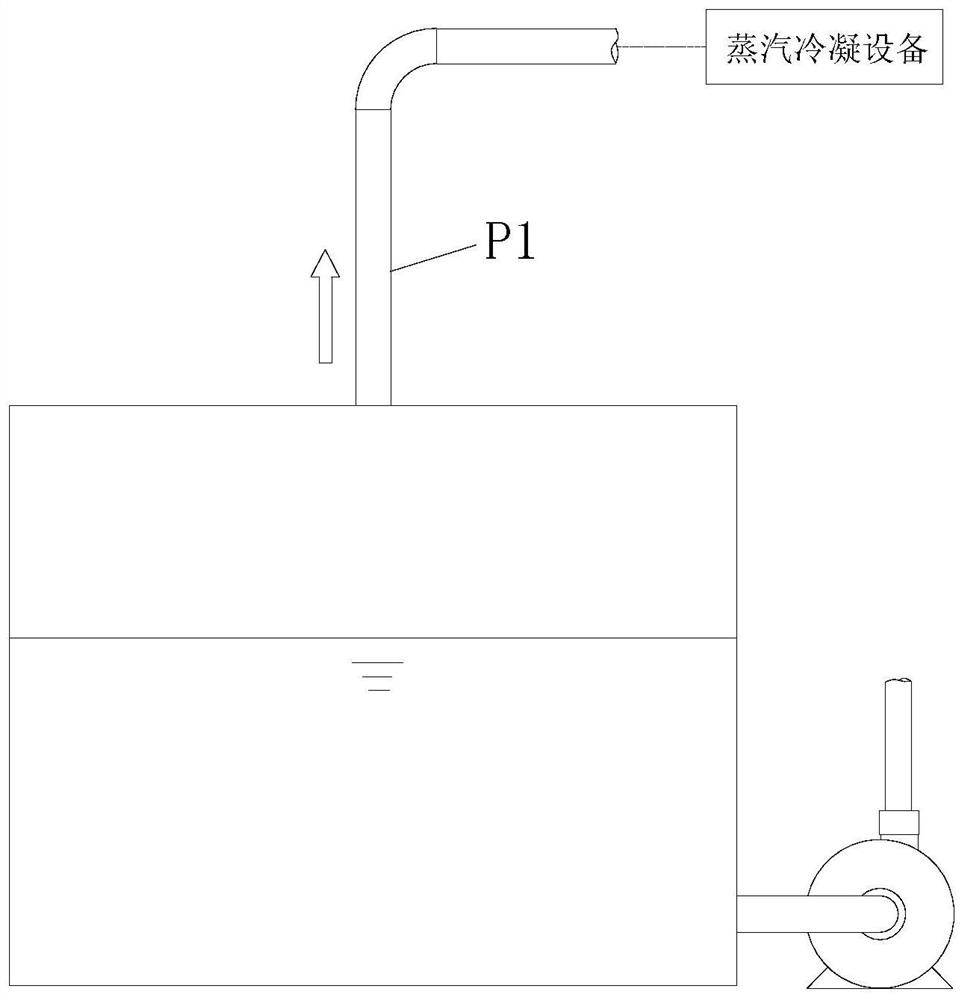
A technology of overflow device and condensate tank, which is applied in steam/steam condensers, sealing devices of heat exchangers, lighting and heating equipment, etc., can solve the problems of pressure rise at P1 of the pipeline and damage to steam condensing equipment, etc., to ensure safe effect

Pending Publication Date: 2022-07-22
苏州荣轩环保有限公司
View PDF0 Cites 0 Cited by
  • Summary
  • Abstract
  • Description
  • Claims
  • Application Information

AI Technical Summary

Problems solved by technology

When the discharge at the end of the steam pipeline P1 or the steam treatment equipment is not working normally, the possible reason is that the steam treatment equipment is not turned on or the processing capacity is insufficient, which will cause the pressure at the pipeline P1 to continue to rise, and finally infinitely close to the steam pressure at the steam trap, and finally It will cause steam to be discharged through the pipe at the condensate discharge pump. At the same time, the pressure in the steam pipe P1 is too high, which may damage the steam condensing equipment

Method used


Image

  • Safe overflow device of condensate water collecting tank
  • Safe overflow device of condensate water collecting tank
  • Safe overflow device of condensate water collecting tank

Examples


Embodiment 2

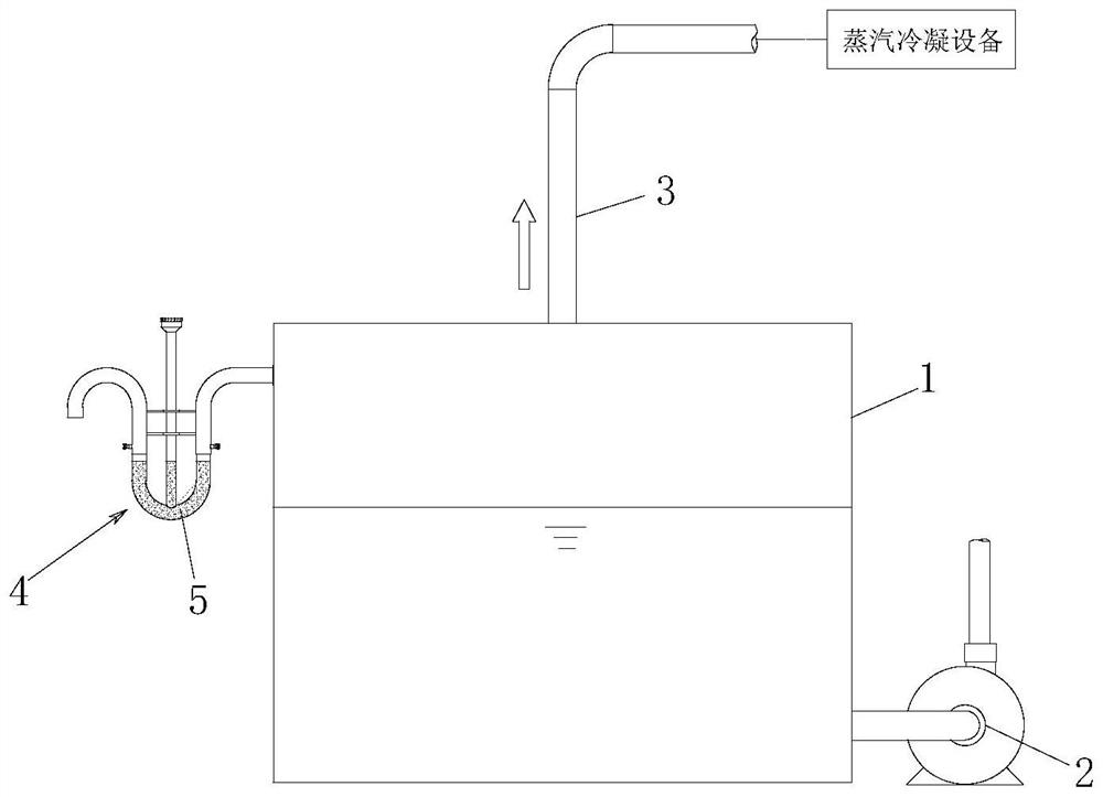
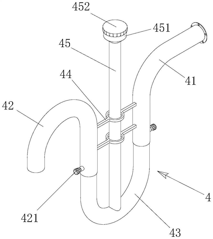
[0031] refer to Figure 2-5 , as another preferred embodiment of the present invention, the difference from Embodiment 1 is that the overflow pipe 4 adopts a U-shaped pipe with adjustable depth, and the overflow pipe 4 includes a connecting pipe section 41 , a U-shaped pipe section 42 and an overflow pipe section 43 , the connecting pipe section 41 and the overflow pipe section 43 are arranged at the same height on both sides of the U-shaped pipe section 42 in a way of plugging, and a fixing frame 44 is arranged between the connecting pipe section 41 and the overflow pipe section 43, and the fixing frame 44 will connect the pipe section 41 and the overflow pipe section. 43 is fixed, on the one hand, it can ensure that the connecting pipe section 41 and the overflow pipe section 43 are always in the same height state, and on the other hand, the U-shaped pipe section 42 can be adjusted up and down. One end of the connecting pipe section 41 away from the U-shaped pipe section 42 ...

Embodiment 3

[0033] refer to Figure 2-5 , as another preferred embodiment of the present invention, the difference from Embodiment 1 or 2 is that the "U"-shaped bottom end of the overflow pipe 4 is connected with a water injection pipe 45, and the top of the water injection pipe 45 is provided with a water injection port 451, The water injection port 451 is in the shape of a funnel, and the water injection port 451 is provided with a cover 452 . After the liquid sealing area 5 is discharged from the overflow pipe 4 and the steam discharge of the steam pipe 3 is normal again, the water injection pipe 45 is provided for adding plugging liquid to form the liquid sealing area 5 again. The water injection pipe 45 is a transparent pipe, so as to facilitate the observation of the amount of the plugging liquid added.


PUM


Abstract

The invention discloses a safety overflow device for a condensate water collecting tank, and relates to the technical field of condensate water collecting tanks, the safety overflow device comprises a condensate water tank, the top of the condensate water tank is connected with a steam pipeline, one side of the bottom of the condensate water tank is connected with a water pump, one side of the top of the condensate water tank is connected with an overflow pipeline, and the overflow pipeline is of a U-shaped structure. And a liquid sealing and filling area is arranged in the overflow pipeline. The condensate water tank has the automatic pressure relief capacity, the safety protection effect on steam treatment equipment is achieved, and meanwhile the safety of the condensate water collecting tank is guaranteed.

Description

technical field [0001] The invention belongs to the technical field of condensed water collection tanks, and in particular relates to a safety overflow device for a condensed water collection tank. Background technique [0002] At present, in all factories using steam, the condensed water is discharged at the same time as soda and water, and is discharged to a low-level condensed water collection tank. At the same time as the condensed water is collected, in order to eliminate the white smoke phenomenon, see figure 1 , In the existing condensed water collection tank, the steam is collected and then condensed, and the condensed water collected in the condensed water collection tank is directly pumped away or overflowed away. When the discharge at the end of the steam pipe P1 or the steam treatment equipment is not working properly, the possible reason is that the steam treatment equipment is not turned on or the treatment capacity is insufficient, which will cause the pressur...

Claims


Application Information

Patent Timeline
Patent Type & Authority Applications(China)
IPC IPC(8): F28B9/08F28F9/26F28F11/00
CPCF28B9/08F28F9/266F28F11/00
Inventor 武善国
Owner 苏州荣轩环保有限公司
Why Eureka
Try Eureka