Stator automatic winding and embedding shaping machine of synchronous motor

A technology for synchronous motors and shaping machines, which is applied in the direction of electric components, manufacturing motor generators, manufacturing stator/rotor bodies, etc., and can solve problems such as low production efficiency

Active Publication Date: 2022-07-22
JIANGSU DAZHONG ELECTRIC MOTOR
View PDF8 Cites 0 Cited by
  • Summary
  • Abstract
  • Description
  • Claims
  • Application Information

AI Technical Summary

Problems solved by technology

[0003] The stator shaping machine is suitable for the coil shaping of small and medium-sized stators, and the existing publication number is: "A kind of motor stator shaping machine" disclosed by CN209627175U, the stator is put into the machine manually, and taken out after the stator shaping is completed. , before putting in the next stator to be shaped, therefore, resulting in low production efficiency and unable to achieve a fast and convenient shaping process for the stator

Method used


Image

  • Stator automatic winding and embedding shaping machine of synchronous motor
  • Stator automatic winding and embedding shaping machine of synchronous motor
  • Stator automatic winding and embedding shaping machine of synchronous motor

Examples


Embodiment 1

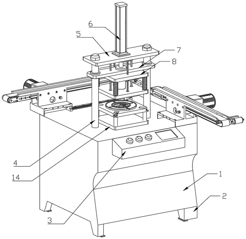
[0032] like Figure 1-Figure 7 As shown in the figure, the present invention provides an automatic winding and shaping machine for the stator of a synchronous motor, including a body 1, a base 2 is arranged on the walls around the bottom of the body 1, a controller 3 is arranged on the upper wall at the front end of the body 1, and the body 1 The top is symmetrically provided with two guide columns 4, the top of the two guide columns 4 is provided with a top plate 5, the top center of the top plate 5 is provided with a first cylinder 6, and the two guide columns 4 are located below the top plate 5 with a mounting plate 7 , the bottom of the mounting plate 7 is provided with a first fixed plate 8, the bottom of the first fixed plate 8 is provided with a first fixed shaft 9, the bottom of the first fixed shaft 9 is provided with a first limit block 10, and the first fixed shaft 9 is provided with A first pressing plate 11 is provided, a connecting ring 12 is arranged above the f...

Embodiment 2

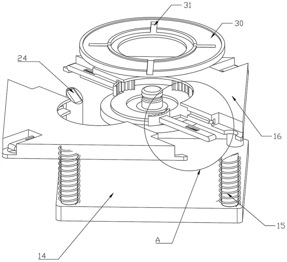
[0034]The bottom of the second fixed shaft 15 is fixedly installed on the top side of the second fixed plate 14 , the top of the second fixed shaft 15 is provided with a first chute 24 , the shaft body of the second fixed shaft 15 is sleeved with a compression spring, and the second pressure plate 16 The second fixing shaft 15 is inserted through the through holes of the outer side wall. The top of the second fixing shaft 15 is fixedly mounted with a third limiting block 30 . The top of the third limiting block 30 is provided with a number of limiting grooves 31 . A shaping groove 25 is formed at the center of the top of the second pressure plate 16 , a plurality of expansion grooves 26 are formed on the inner side of the shaping groove 25 , a second limit block 27 is fixedly installed on one side of the expansion groove 26 , and a mounting groove 28 is formed on one side of the connecting rod 17 , a first fixing rod 29 is fixedly installed between the inner walls of the instal...


PUM


Abstract

The automatic winding and embedding shaping machine comprises a machine body, bases are arranged on the peripheral wall bodies of the bottom of the machine body, a controller is arranged on the wall body above the front end of the machine body, two guide columns are symmetrically arranged at the top of the machine body, and a top plate is arranged at the tops of the two guide columns; a first air cylinder is arranged in the center of the top of the top plate, a mounting plate is arranged at the positions, below the top plate, of the two guide columns, a first fixing plate is arranged at the bottom of the mounting plate, and first fixing shafts are arranged on the periphery of the bottom of the first fixing plate. The invention discloses an automatic winding and embedding shaping machine for a stator of a synchronous motor, relates to the technical field of stator shaping equipment, and is convenient for synchronously lifting the shaped stator after a first pressing plate is pressed down and lifted through the arrangement of an L-shaped mounting rod and a pressing block. And through the arrangement of a connecting ring and an adjusting rod, when the first pressing plate moves upwards, the stator limited by the pressing block is automatically released through the first fixing plate.

Description

technical field [0001] The invention relates to the technical field of stator shaping equipment, in particular to an automatic winding and embedding shaping machine for a synchronous motor. Background technique [0002] The stator is the stationary part of the motor or generator. The stator consists of three parts: the stator core, the stator winding and the frame. The main function of the stator is to generate a rotating magnetic field, and the main function of the rotor is to be cut by magnetic lines of force in the rotating magnetic field to generate (output) current. Various types of stator primary shaping machines are used. [0003] The stator shaping machine is suitable for the coil shaping of small and medium-sized stators, and the existing publication number is: CN209627175U "A Motor Stator Shaping Machine", which is to manually put the stator into the machine, and take it out after the stator shaping is completed. , before putting in the next stator to be shaped, ...

Claims


Application Information

Patent Timeline
Patent Type & Authority Applications(China)
IPC IPC(8): H02K15/00H02K15/02
CPCH02K15/0025H02K15/026
Inventor 周剑李学军朱银波顾增鞠丽华
Owner JIANGSU DAZHONG ELECTRIC MOTOR
Why Eureka
Try Eureka