
Minimally invasive cholecystic duct probing mirror

A cystic duct and flexible tube technology, which is applied in the field of minimally invasive cystic duct exploration scope, can solve the problems of uncombined, unexplorable sampling and drug treatment operations, and single-channel device channels, etc. The effect of functionality and practicality

Inactive Publication Date: 2022-07-26
ZHENGZHOU CENT HOSPITAL
View PDF0 Cites 0 Cited by
  • Summary
  • Abstract
  • Description
  • Claims
  • Application Information

AI Technical Summary

Problems solved by technology

[0002] During the gallbladder protection operation in the human body, there are diseases such as gallstones, fibroids, and tumors in the gallbladder and biliary tract. During the operation, the field of view of the probe mirror is required, and special surgical instruments are also required. The existing technology is to use a puncture device, an operating channel, and an obturator. It is used as a mechanical channel for exploration in instruments, etc., but the defect is that the channel of this type of instrument is a single-channel structure. During the operation, only a single operation of spying or mechanical operation can be performed, and the two cannot be effectively combined. At the same time, the existing gallbladder exploration structure Effective sampling and drug administration cannot be performed on the probing site during use. Based on this, the present invention provides a minimally invasive cystic duct exploration mirror to solve the problems raised in the above-mentioned background technology

Method used


Image

  • Minimally invasive cholecystic duct probing mirror
  • Minimally invasive cholecystic duct probing mirror
  • Minimally invasive cholecystic duct probing mirror

Examples


Embodiment Construction

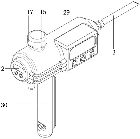
[0029] The present invention will be further elaborated and described below in conjunction with specific embodiments and the accompanying drawings:

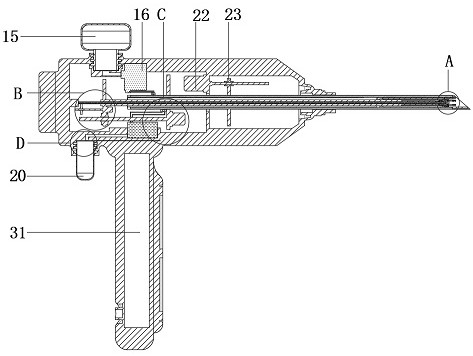
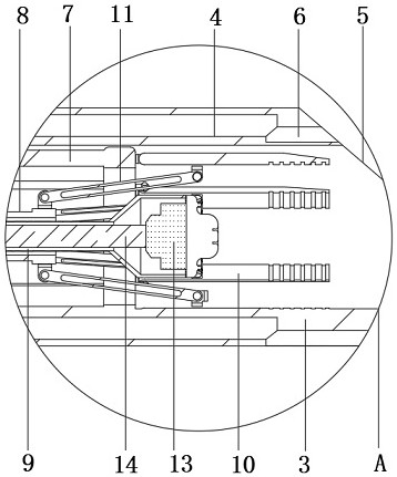
[0030] see Figure 1-8 , the present invention: a minimally invasive cystic duct exploration mirror adopts the technical scheme: comprising a body 1, a main board 2 is fixedly installed at the tail of the body 1, a handle 30 is installed at the bottom of the body 1, and a battery is fixedly installed inside the handle 30 31. The peripheral side of the handle 30 is respectively provided with a central control panel and a charging interface, one end of the charging interface is electrically connected to the battery 31, and the port of the central control panel is electrically connected to the main board 2;

[0031] The battery 31 is a rechargeable battery 31 , the function of the battery 31 is to supply power to the power using mechanism of the device, the function of the charging interface is to supply power to the interior of the...


PUM


Abstract

The minimally invasive cholecystic duct probing mirror comprises a machine body, a main board is fixedly installed at the tail of the machine body, a drug administration module is fixedly installed at the top of the machine body, a sampling module is fixedly installed at the bottom of the machine body, a needle cylinder is slidably connected to the axis position in the machine body, and an annular cavity is fixedly formed in the needle cylinder; one end of the dosing module and one end of the sampling module are both fixedly communicated with the annular cavity, a puncture inclined plane is fixedly arranged on the end face of the needle cylinder, a group of through holes which are distributed in a circumferential array and communicated with the annular cavity are formed in the surface of the puncture inclined plane, an outer cylinder is slidably connected to the inner wall of the needle cylinder, and an inner cylinder is slidably connected to the inner wall of the outer cylinder; the inner wall of the inner cylinder is slidably connected with a core cylinder. Through the design of the needle cylinder, the outer cylinder, the inner cylinder, the core cylinder and other structures, the visual field exploration operation in the gallbladder duct can be efficiently completed in a minimally invasive mode, and the exploration device changes a single structure of a traditional exploration device into a double structure.

Description

technical field [0001] The invention relates to the technical field of medical aids, in particular to a minimally invasive cystic duct exploration scope. Background technique [0002] During the gallbladder protection operation in the human body, there are diseases such as stones, fibroids, tumors in the gallbladder and biliary tract. During the operation, the field of view of the exploration mirror is required, and special surgical instruments are also required. It is used as an exploration mechanical channel in the instrument and so on. The disadvantage is that the channels of such instruments are all single-channel structures. During the operation, only a single prying or mechanical operation can be performed, and the two cannot be effectively combined. At the same time, the existing gallbladder exploration structure When in use, effective sampling and drug administration cannot be performed at the probe site. Based on this, the present invention provides a minimally inva...

Claims


Application Information

Patent Timeline
Patent Type & Authority Applications(China)
IPC IPC(8): A61B17/00A61B90/00A61B90/30A61B10/04A61M31/00
CPCA61B17/00234A61B90/361A61B90/30A61B10/04A61M31/00A61B2017/00296
Inventor 罗红杰季春勇刘东亮
Owner ZHENGZHOU CENT HOSPITAL
Learn More