Backlight module and display device

A technology for backlight modules and optical components, which is applied in optics, nonlinear optics, instruments, etc., can solve the problems of difficulty in promoting the development of borderless liquid crystal display devices and the width of the frame, and achieve the effect of increasing the area and expanding the light-emitting area.

Pending Publication Date: 2022-07-29
MIANYANG HKC OPTOELECTRONICS TECH CO LTD +1
View PDF14 Cites 0 Cited by
  • Summary
  • Abstract
  • Description
  • Claims
  • Application Information

AI Technical Summary

Problems solved by technology

[0003] The backlight module includes a backplane and a middle frame. The backplane in a traditional backlight module usually includes a bottom plate and a side plate protruding from the edge of the bottom plate. The middle frame is nested outside the side plate, so that the frame size of the backlight module is not less than The sum of the width of the middle frame and the thickness of the side panels of the back panel makes the frame of the backlight module wider, making it difficult to promote the development of frameless LCD devices

Method used


Image

  • Backlight module and display device
  • Backlight module and display device
  • Backlight module and display device

Examples


Embodiment 1

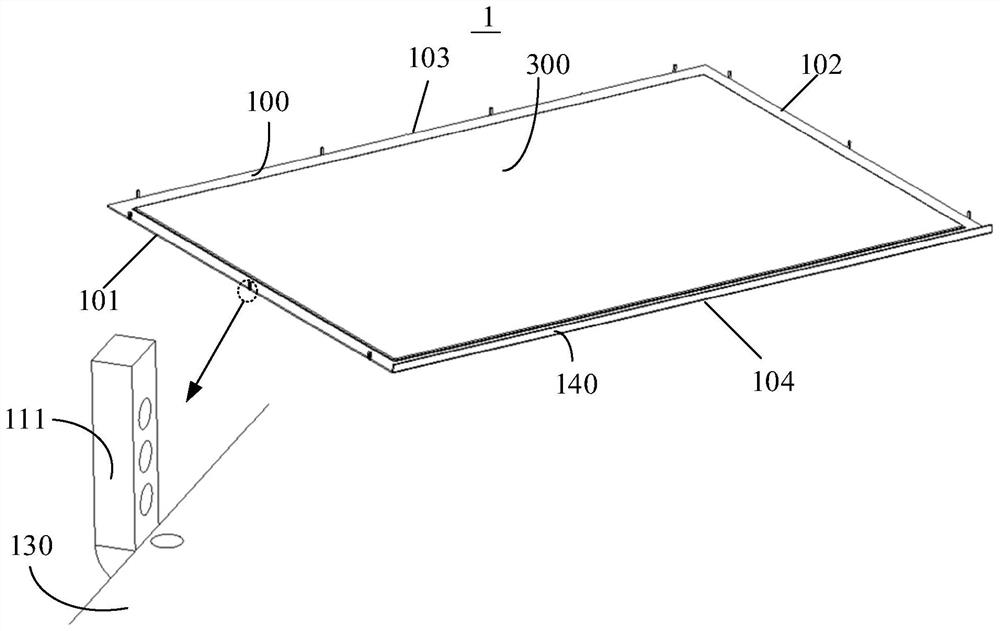
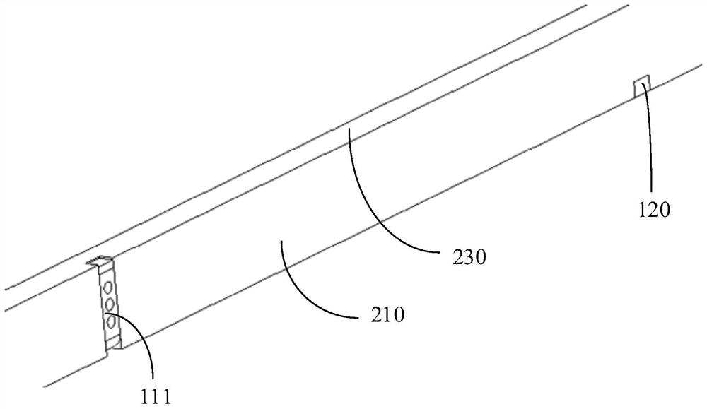
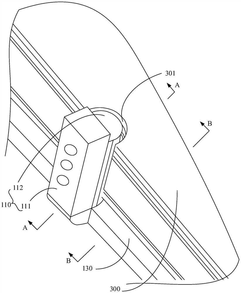
[0036] In the embodiments of this application, please refer to figure 1 and figure 2 , the backlight module 1 includes a backplane 100, a middle frame 200 and an optical assembly, the backplane 100 includes a bottom plate 130, the middle frame 200 includes a support plate 230 and a side plate assembly, the support plate 230 is arranged opposite to the bottom plate 130, and the side plate assembly is connected At the edge of the support plate 230 and extending toward the direction of the bottom plate 130, the bottom plate 130, the support plate 230 and the side plate components together form an installation space, the optical components are arranged in the installation space, and a part of the edge of at least one side of the bottom plate 130 is formed. A blocking wall assembly 110 is protruded toward the direction of the support plate 230 , and an escape space is formed above the other part of the edge; The optical component includes an optical film 300, a part of the edge o...

Embodiment 2

[0068] The present application also proposes a display device, such as Figure 8 As shown, the display panel 2 includes a display panel 2 and a backlight module 1, and the specific structure of the backlight module 1 refers to the above-mentioned embodiments. All the beneficial effects brought by the technical solutions of the examples are not repeated here. The backlight module 1 is disposed on the light incident side of the display panel 2 to provide a light source to the display panel 2 . Specifically, the display panel 2 may be directly adhered to the support plate 230 of the middle frame 200 by double-sided tape.


PUM


Abstract

The invention discloses a backlight module and a display device. The backlight module comprises a back plate, a middle frame and an optical assembly, the back plate comprises a bottom plate, the middle frame comprises a supporting plate and a side plate assembly, the supporting plate and the bottom plate are oppositely arranged, the side plate assembly is connected to the edge of the supporting plate and extends in the direction of the bottom plate, and the bottom plate, the supporting plate and the side plate assembly jointly define a mounting space; the optical assembly is arranged in the installation space, a retaining wall assembly is arranged on a part of the edge of at least one side edge of the bottom plate in a protruding mode in the direction towards the supporting plate, and an avoiding space is formed above the other part of the edge. The side plate assembly comprises a first side plate, and the first side plate and the retaining wall assembly are matched in an inserted mode in the direction perpendicular to the bottom plate. The optical assembly comprises an optical film, an opening groove is formed in part of the edge of the optical film, the retaining wall assembly is embedded into the opening groove, and the other part of the edge of the optical film extends into the avoiding space. According to the technical scheme, the narrow frame effect of the backlight module can be achieved, and the brightness area can be enlarged.

Description

technical field [0001] The present application relates to the field of display technology, and in particular, to a backlight module and a display device using the backlight module. Background technique [0002] With the advancement of science and technology, the development of ultra-narrow bezels or even borderless liquid crystal display devices has become a trend of current liquid crystal displays. Liquid crystal display devices include a backlight module and a display panel. The backlight module is located on the backlight side of the display panel. The panel provides the light source. [0003] The backlight module includes a back plate and a middle frame. The back plate in a traditional backlight module usually includes a bottom plate and a side plate protruding from the edge of the bottom plate. The middle frame is nested outside the side plate, so that the frame size of the backlight module is not smaller than The sum of the width of the middle frame and the thickness ...

Claims


Application Information

Patent Timeline
IPC IPC(8): G02F1/13357G02F1/1333
CPCG02F1/133608G02F1/133314G02F1/133317
Inventor 何江郑浩旋
Owner MIANYANG HKC OPTOELECTRONICS TECH CO LTD
Why Eureka
Try Eureka