Split type heat dissipation structure of LED display screen module and using method of split type heat dissipation structure
A technology of LED display and heat dissipation structure, which is applied in the installation of support structure, cooling/ventilation/heating transformation, identification device, etc., can solve the problems of cumbersome process and inability to transmit heat from LED display module, and achieves simple and convenient operation, The effect of easy maintenance and avoidance of damage
- Summary
- Abstract
- Description
- Claims
- Application Information
AI Technical Summary
Problems solved by technology
Method used
Image

Examples
Embodiment 1
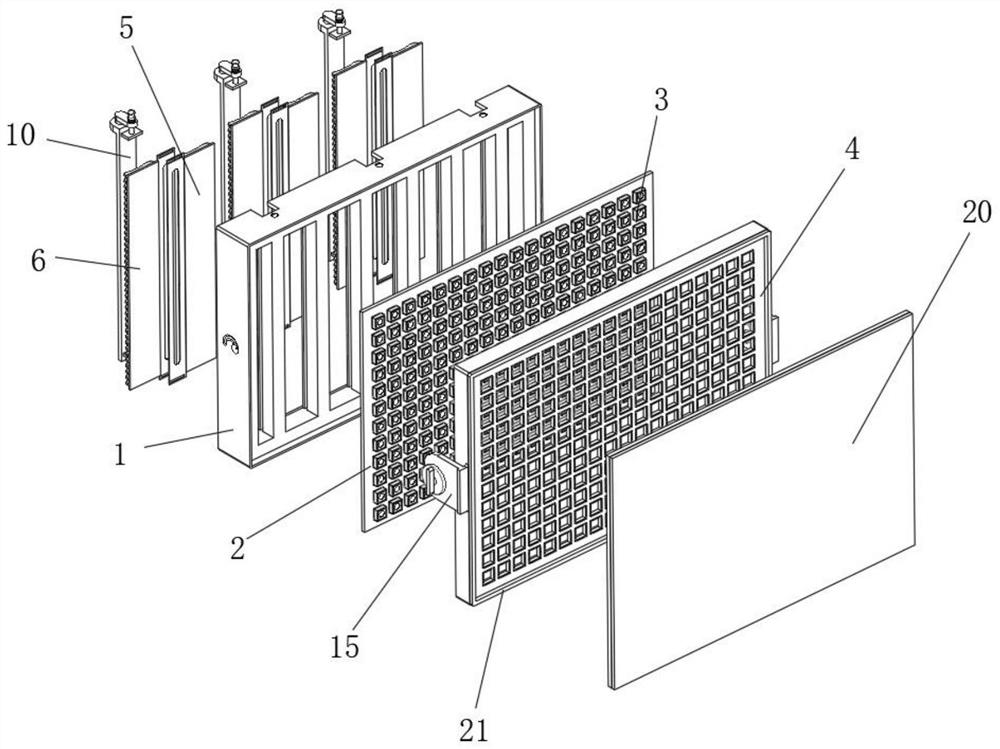
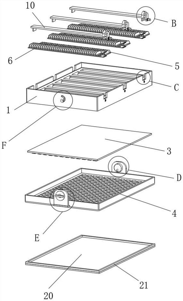
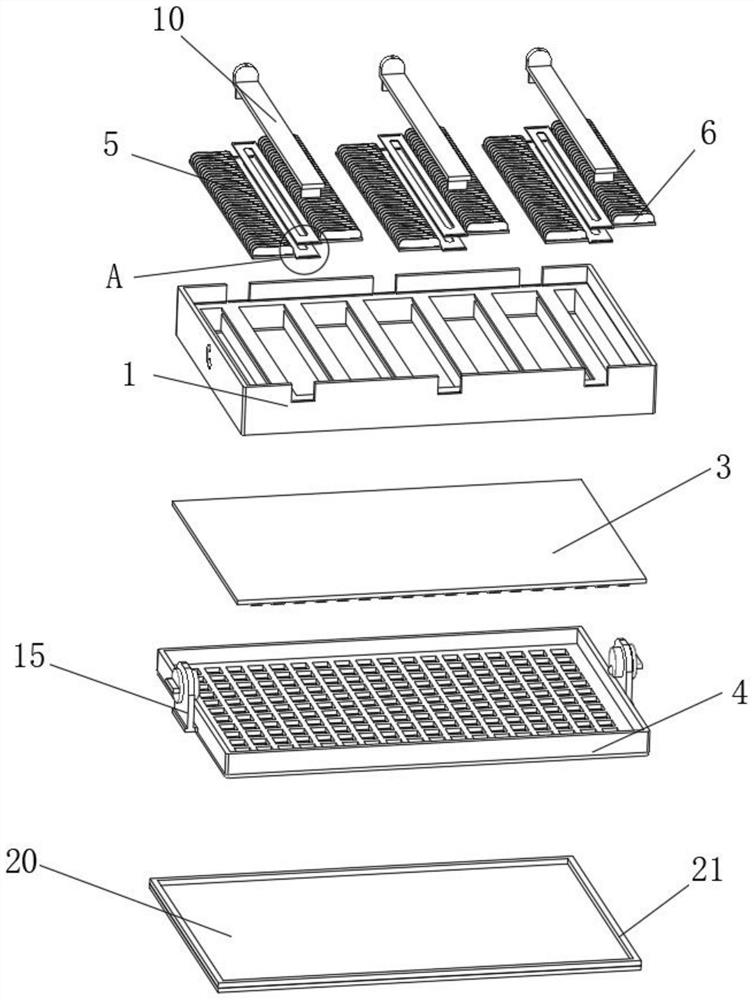
[0033] Example 1, please refer to Figure 1-6 , The present invention provides a technical solution: a split heat dissipation structure of an LED display module, comprising an outer casing 1, a PCB board 2 is arranged inside the outer casing 1, the surface of the PCB board 2 is fixed with lamp beads 3, and the outer casing One side of the body 1 is provided with an outer frame 4, the side of the outer casing 1 opposite to the outer frame 4 is provided with a heat dissipation fin a5, one side of the heat dissipation fin a5 is provided with a heat dissipation fin b6, the heat dissipation fin a5 and the heat dissipation fin One side of the sheet b6 is fixedly installed with a gasket 7, and the gasket 7 is respectively installed on the bottom surface and the top surface of the heat dissipation fin a5 and the heat dissipation fin b6 in a staggered state. , so that the cooling fin a5 and the cooling fin b6 can be laid flat together, and the surface of the gasket 7 is also provided w...
Embodiment 2
[0035] Example 2, please refer to figure 2 and Figure 8 , a connecting device is provided between the outer casing 1 and the outer frame 4, and the connecting device includes an elastic block 15, the elastic blocks 15 are fixedly installed on both sides of the outer frame 4, and a rotating rod 16 is rotated inside the elastic block 15. One end has a protruding structure, and by setting the protruding rotating rod 16, it is convenient for people to rotate the rotating rod 16.
[0036] see figure 2 , Figure 7 and Figure 9 One side of the rotating rod 16 is fixed with a positioning bead 17, and both sides of the outer casing 1 are provided with positioning holes 18. The shape of the positioning holes 18 is spherical. By setting the spherical positioning holes 18, the positioning beads 17 are fitted When the positioning bead 17 is affected by external force, it can be removed from the positioning hole 18. The surface of the outer casing 1 is provided with an arc-shaped gr...
Embodiment 3
[0037] Example three, please refer to Figure 1-3 , the outer surface of the outer frame 4 is provided with a protective device, the protective device includes a cover plate 20, the cover plate 20 is arranged on one side of the outer frame 4, and the cover plate 20 is provided to protect the lamp beads 3.
[0038] see Figure 1-3, the surfaces of the cover plate 20 and the outer frame 4 are equipped with magnets 21, and the magnets 21 are respectively fixed and installed around the cover plate 20 and the outer frame 4. By installing the magnets 21 around the cover plate 20 and the outer frame 4, the magnets 21 are added. The contact area between them enables the magnet 21 to be firmly adsorbed.
[0039] A method of using a split heat dissipation structure for an LED display module, comprising the following steps:
[0040] Step 1: In the process of installing the cooling fin a5 and the cooling fin b6, first, stack the cooling fin a5 and the gasket 7 on the side of the cooling...
PUM
 Abstract
Description
Claims
Application Information