Supercharge Your Innovation With Domain-Expert AI Agents!

Carbon monoxide leakage alarm device and method

A carbon monoxide and alarm device technology, applied in alarms, heating methods, instruments, etc., can solve problems such as user hazards, unrecognizable alarms, user hazards, etc., and achieve the effect of reducing CO poisoning

Pending Publication Date: 2022-07-29
NANOKEM CO LTD
View PDF20 Cites 0 Cited by
  • Summary
  • Abstract
  • Description
  • Claims
  • Application Information

AI Technical Summary

Problems solved by technology

Therefore, the existing CO leakage detection device will only issue an alarm when the reference time according to the level is exceeded. Even if a large amount of CO suddenly leaks due to damage to the chimney, the alarm will only be issued when the reference time is exceeded. Issues where users may be at risk
[0010] In addition, the existing CO leakage detection device is installed in a place separate from the user's living space, so even if the alarm sounds, it may not be heard, and when sleeping, there is a problem that the alarm cannot be recognized before CO poisoning, and when the CO leakage detection device When the alarm function of the alarm function fails, there is a problem that it can be directly poisoned by CO
[0011] In addition, even after the user hears the alarm of the CO leakage detection device and shuts down the operation of the boiler, or the CO leakage detection device automatically shuts down the operation of the boiler, CO remains in the boiler, so that CO inside the boiler may leak into the user's residence. space, so there is still the problem of possible harm to users
[0012] In addition, the existing CO leakage detection device issues an alarm or simply terminates the operation of the boiler according to the detection of CO leakage, so there is a problem that in order to remove the CO that has diffused into the user's living space, the user must directly perform the process by opening a window in the living space. Ventilation issues, which present a potential ongoing hazard to CO exposed users in a comatose state

Method used


Image

  • Carbon monoxide leakage alarm device and method
  • Carbon monoxide leakage alarm device and method
  • Carbon monoxide leakage alarm device and method

Examples


Embodiment Construction

[0039] Hereinafter, the structure and operation of the carbon monoxide leakage warning device and carbon monoxide discharge system according to the present invention will be described in detail with reference to the accompanying drawings, and the carbon monoxide leakage warning method and carbon monoxide discharge method performed in the above-mentioned device will be described.

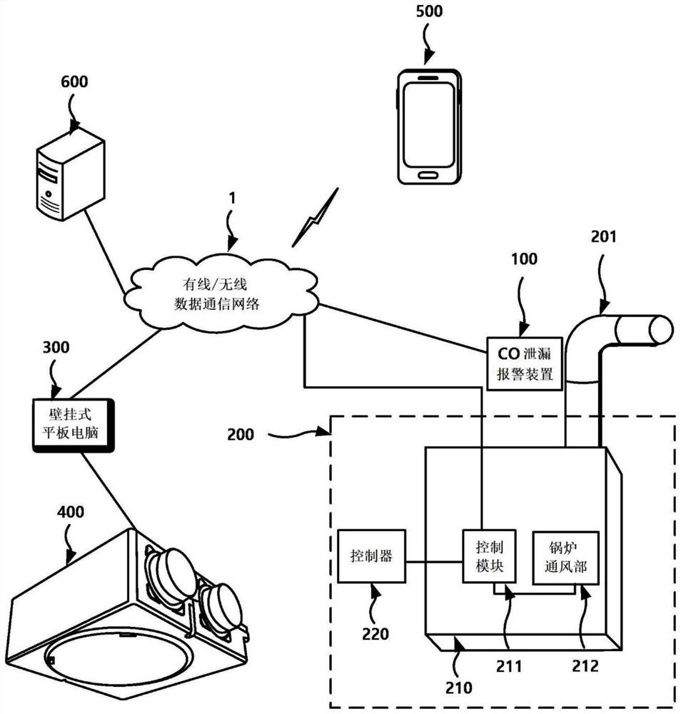
[0040] figure 1 is a diagram showing the structure of a carbon monoxide discharge system using a carbon monoxide leakage alarm device according to the present invention.

[0041] refer to figure 1 , the carbon monoxide emission system utilizing the carbon monoxide leakage alarm device according to the present invention includes a carbon monoxide (CO) leakage alarm device 100 and a boiler 200, and according to an embodiment, may further include a wall-mounted tablet computer 300, a ventilation system 400, a user mobile terminal 500 and The related agency server 600 .

[0042] The above-mentioned CO ...


PUM


Abstract

The present invention relates to a device and a method for alarming carbon monoxide leakage, and more particularly, to a device and a method for alarming carbon monoxide leakage, which are operated on the basis of Internet of Things (Internet of Things), and which, after detecting carbon monoxide (CO) leaked due to breakage of a boiler chimney, give an alarm by means of two or more of a carbon monoxide alarm device, a boiler controller, a wall-mounted tablet computer, and the like, and when the leakage is confirmed, give an alarm by means of the alarm device, the boiler controller, the wall-mounted tablet computer, and the like, and give an alarm by means of the alarm device, the boiler controller, the wall-mounted tablet computer, and the like. The invention relates to a carbon monoxide leakage alarm device and a carbon monoxide leakage alarm method, which automatically perform boiler ventilation and indoor air ventilation, and directly notify CO leakage to CO leakage related mechanisms and users.

Description

technical field [0001] The invention relates to a carbon monoxide leakage alarm device and method, and more particularly, to an operation based on the Internet of Things (Internet of Thing: IoT), and after detecting the carbon monoxide (Carbonmonoxide: CO) leaked due to the damage of the boiler chimney , The alarm is issued through two or more of carbon monoxide alarm devices, boiler controllers, wall-mounted tablet PCs (Wallpad), etc. When a leak is confirmed, boiler ventilation and indoor air ventilation are automatically performed, and directly related to CO leakage. A carbon monoxide leakage alarm device and method for notifying a user of CO leakage. Background technique [0002] In general, boilers can adjust the temperature of water and indoors by burning fuels such as coal, kerosene, and diesel containing carbon components. [0003] Boilers generate carbon monoxide (CO) during the combustion of carbon-containing fuels. CO is a colorless, odorless, tasteless and non-...

Claims


Application Information

Patent Timeline
Patent Type & Authority Applications(China)
IPC IPC(8): F24H9/20F24H15/12F24H15/395F24F11/38F24F11/52F24F11/58G08B21/14G08B25/00G08B25/10F24F110/72
CPCF24F2110/72F24F11/0001F24F11/32F24H15/12G08B21/14G08B25/005F24H9/2042F24F2221/183F23N2900/05001F24H9/2035F23N5/242F23J2213/70G08B25/007G08B25/10
Inventor 崔荣桓河省安张炡载
Owner NANOKEM CO LTD
Features
  • R&D
  • Intellectual Property
  • Life Sciences
  • Materials
  • Tech Scout
  • Unparalleled Data Quality
  • Higher Quality Content
  • 60% Fewer Hallucinations
Learn More