
Five-axis numerical control machining center with high-rigidity transmission chain structure and thermal compensation method

A machining center and transmission chain technology, applied in metal processing equipment, metal processing mechanical parts, manufacturing tools, etc., can solve the problems of low temperature, deformation, affecting performance, etc., and achieve the effect of avoiding excessive temperature difference

Active Publication Date: 2022-08-02
FOSHAN PRATIC CNC SCI & TECH
View PDF7 Cites 0 Cited by
  • Summary
  • Abstract
  • Description
  • Claims
  • Application Information

AI Technical Summary

Problems solved by technology

[0003] When grinding, drilling, cutting and other operations on the parts, the friction of the machining center will inevitably generate a lot of heat, and the parts themselves are composed of steel parts. When the temperature rises and changes, thermal expansion and contraction will occur later. phenomenon, while the temperature of the processed part is higher for the grinding part, but the temperature for the rest of the part is not very high, which causes local overheating of the part, which may cause slight deformation and affect the overall performance

Method used


Image

  • Five-axis numerical control machining center with high-rigidity transmission chain structure and thermal compensation method
  • Five-axis numerical control machining center with high-rigidity transmission chain structure and thermal compensation method
  • Five-axis numerical control machining center with high-rigidity transmission chain structure and thermal compensation method

Examples


Embodiment 1

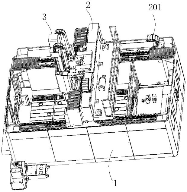
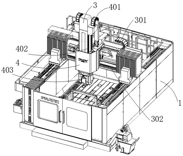
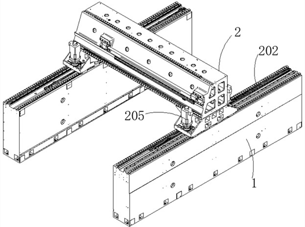
[0047] refer to Figure 1-14 , a five-axis CNC machining center with a high-rigidity transmission chain structure, including a symmetrical column 1, a beam 2 is slidably connected to the column 1, a first transmission chain 201 is connected between the column 1 and the beam 2, and the beam 2 slides on A moving vertical plate 3 is connected, a second transmission chain 301 is connected between the beam 2 and the moving vertical plate 3, a lifting plate 4 is slidably connected to the moving vertical plate 3, and a third connecting plate is connected between the moving vertical plate 3 and the lifting plate 4. The transmission chain 401, the lifting plate 4 is connected with the processing head 403, and also includes:

[0048] The base 7 is fixedly connected between the two uprights 1;

[0049] A plurality of suction pipes 9 with solenoid valves are fixedly connected to the base 7;

[0050] A plurality of thin air blowing tubes 10 with solenoid valves are fixedly connected to t...

Embodiment 2

[0059] refer to Figure 1-14 , a five-axis CNC machining center with a high-rigidity transmission chain structure, including a symmetrical column 1, a beam 2 is slidably connected to the column 1, a first transmission chain 201 is connected between the column 1 and the beam 2, and the beam 2 slides on A moving vertical plate 3 is connected, a second transmission chain 301 is connected between the beam 2 and the moving vertical plate 3, a lifting plate 4 is slidably connected to the moving vertical plate 3, and a third connecting plate is connected between the moving vertical plate 3 and the lifting plate 4. The transmission chain 401, the lifting plate 4 is connected with the processing head 403, and also includes:

[0060] The base 7 is fixedly connected between the two uprights 1;

[0061] A plurality of suction pipes 9 with solenoid valves are fixedly connected to the base 7;

[0062] A plurality of thin air blowing tubes 10 with solenoid valves are fixedly connected to t...

Embodiment 3

[0073] refer to Figure 1-14 , a five-axis CNC machining center with a high-rigidity transmission chain structure, including a symmetrical column 1, a beam 2 is slidably connected to the column 1, a first transmission chain 201 is connected between the column 1 and the beam 2, and the beam 2 slides on A moving vertical plate 3 is connected, a second transmission chain 301 is connected between the beam 2 and the moving vertical plate 3, a lifting plate 4 is slidably connected to the moving vertical plate 3, and a third connecting plate is connected between the moving vertical plate 3 and the lifting plate 4. The transmission chain 401, the lifting plate 4 is connected with the processing head 403, and also includes:

[0074] The base 7 is fixedly connected between the two uprights 1;

[0075] A plurality of suction pipes 9 with solenoid valves are fixedly connected to the base 7;

[0076] A plurality of thin air blowing tubes 10 with solenoid valves are fixedly connected to t...


PUM


Abstract

The invention discloses a five-axis numerical control machining center with a high-rigidity transmission chain structure and a thermal compensation method, and relates to the field of numerical control machine tools. A five-axis numerical control machining center with a high-rigidity transmission chain structure comprises symmetrical stand columns, a cross beam is connected to the stand columns in a sliding mode, a first transmission chain is connected between the stand columns and the cross beam, a movable vertical plate is connected to the cross beam in a sliding mode, and a second transmission chain is connected between the cross beam and the movable vertical plate. A lifting plate is slidably connected to the movable vertical plate, a third transmission chain is connected between the movable vertical plate and the lifting plate, a machining head is connected to the lifting plate, local heat is guided to the whole, heat balance is achieved, and the situation that the performance of parts is affected by stress generated by thermal expansion and cold contraction of the parts due to deformation is avoided.

Description

technical field [0001] The invention belongs to the technical field of numerical control machine tools, and in particular relates to a five-axis numerical control machining center with a high-rigidity transmission chain structure and a thermal compensation method. Background technique [0002] CNC machining center is a high-efficiency automatic machine tool composed of mechanical equipment and CNC system suitable for processing complex parts. The CNC machining center is one of the most productive and widely used CNC machine tools in the world; it concentrates the functions of milling, boring, drilling, tapping and thread cutting on a single device, enabling it to have a variety of machining processes. Means, as the requirements for machining parts are getting higher and higher, five-axis machining is also appearing in machine tools. [0003] When grinding, drilling, cutting and other operations on parts, the friction of the machining center will inevitably generate a lot of...

Claims


Application Information

Patent Timeline
Patent Type & Authority Applications(China)
IPC IPC(8): B23Q1/01B23Q1/25B23Q11/00B23Q11/10
CPCB23Q1/015B23Q1/25B23Q11/10B23Q11/0042Y02P70/10
Inventor 李爱军孟祥东沈成辉唐小琦
Owner FOSHAN PRATIC CNC SCI & TECH
Learn More