Eureka AIR delivers breakthrough ideas for toughest innovation challenges, trusted by R&D personnel around the world.

Tool clamp for oil injection of plastic frame

A tooling fixture and frame technology, which is applied to the injection device and other directions, can solve the problems of increasing production cost, cumbersome operation steps, low work efficiency, etc., and achieve the effects of saving production cost, improving fuel injection efficiency and improving stability.

Active Publication Date: 2022-08-05
DONGGUAN YEJIA ELECTRONICS TECH
View PDF18 Cites 0 Cited by
  • Summary
  • Abstract
  • Description
  • Claims
  • Application Information

AI Technical Summary

Problems solved by technology

[0002] In the fuel injection process of the plastic frame, when it is necessary to spray fuel to a certain part of the product or to a certain area, it is necessary to cover the area that does not need to be sprayed during fuel injection. The traditional masking method is to manually paste it on the plastic frame with paper tape The position that does not need to be sprayed with oil, the paper tape will cover the position that does not need to be sprayed with oil, and the masked paper tape will be torn off after spraying the oil. Fixtures for fuel injection of plastic frames solve the above problems

Method used


Image

  • Tool clamp for oil injection of plastic frame
  • Tool clamp for oil injection of plastic frame
  • Tool clamp for oil injection of plastic frame

Examples


Embodiment Construction

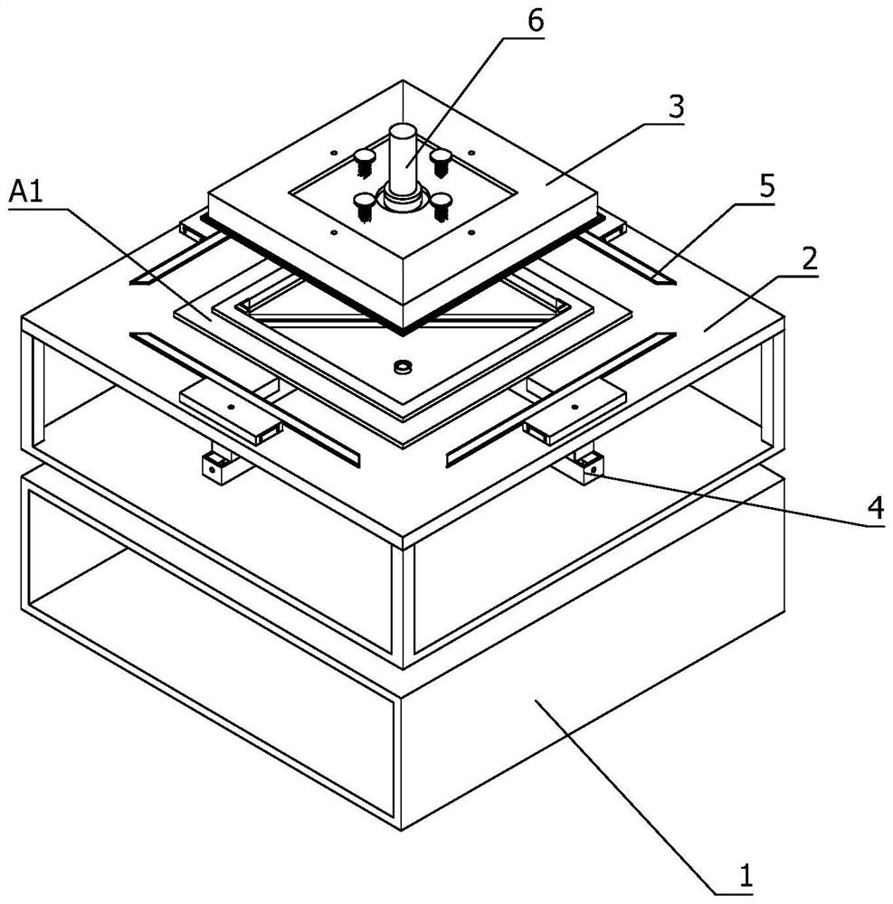
[0044] In order to further understand the features, technical means, and specific objectives and functions of the present invention, the present invention will be described in further detail below with reference to the accompanying drawings and specific embodiments.

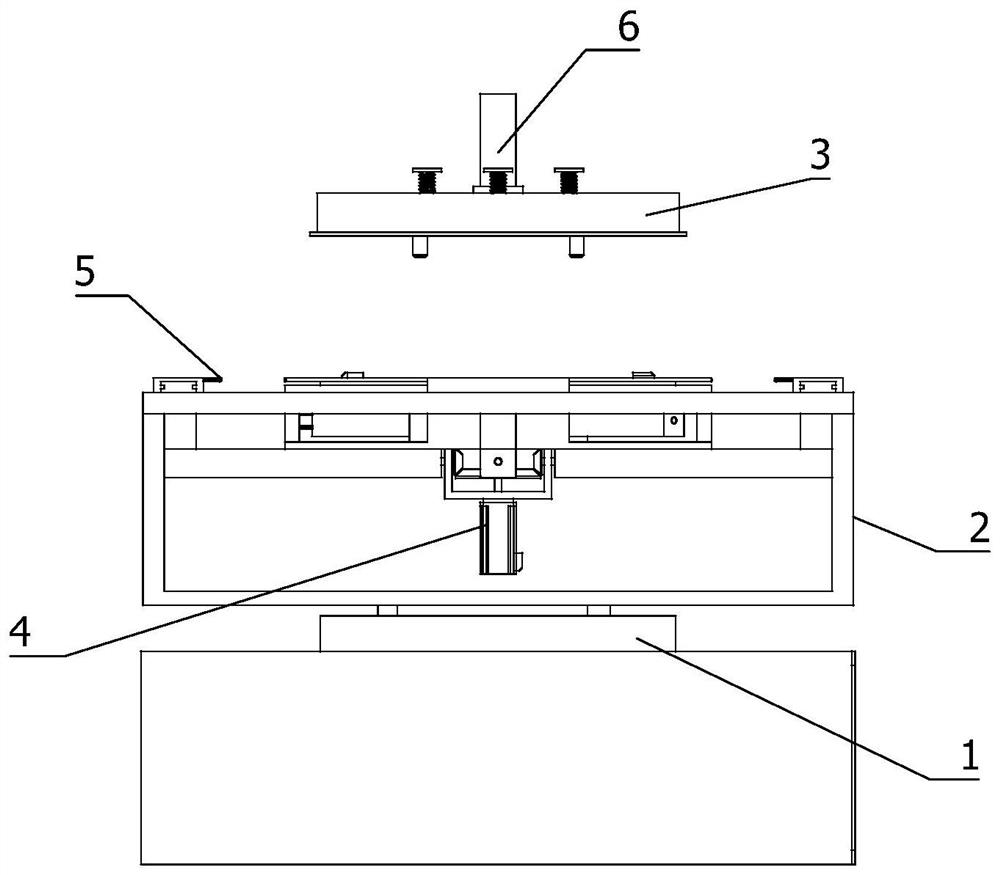
[0045] like figure 1 and 2 shown:

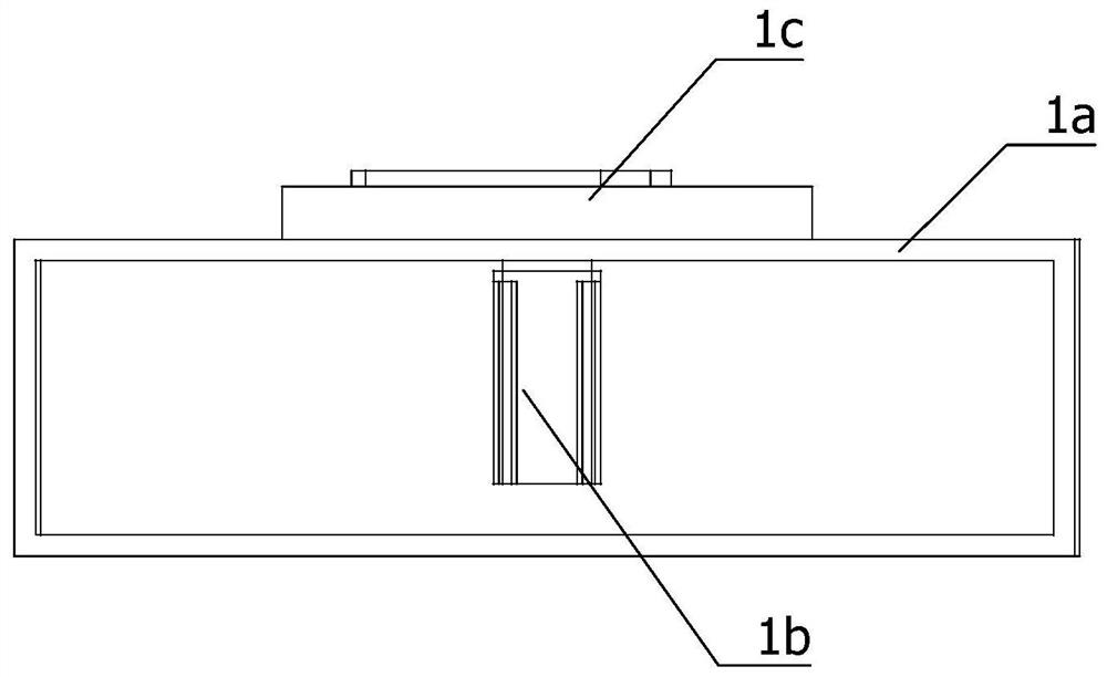
[0046] A tooling fixture for plastic frame oil injection, comprising a rotating base 1, a frame positioning table 2 and a shielding device; the working end of the rotating base 1 is arranged vertically upward; the frame positioning table 2 is fixedly installed on the working end of the rotating base 1; The shielding device is fixedly installed on the frame positioning platform 2; the shielding device includes a synchronous shrinking device 4, a shielding card plate 5, a positioning push head 6 and a shielding cover 3; the synchronous shrinking device 4 is fixedly installed on the frame positioning platform 2, and the synchronous shrinking device 4 There are several working en...


PUM


Abstract

The invention relates to the technical field of plastic frame oil injection, in particular to a tool clamp for plastic frame oil injection. Comprising a rotary base, a frame positioning table and a shielding device, the working end of the rotating base is vertically arranged upwards; the frame positioning table is fixedly mounted at the working end of the rotating base; the shielding device is fixedly mounted on the frame positioning table; the shielding device comprises a synchronous contraction device, a shielding clamping plate, a positioning pushing head and a shielding cover; the synchronous contraction device is fixedly mounted on the frame positioning table and is provided with a plurality of working ends; the shielding clamping plates are provided with a plurality of working ends which are uniformly distributed on the synchronous contraction device; the positioning pushing head is arranged over the frame positioning table, and the working end of the positioning pushing head is vertically arranged downwards. And a plurality of shielding covers are symmetrically spliced and are fixedly mounted on the positioning and pushing device. The plastic frame can be effectively positioned and shielded, the oil injection efficiency is improved, and the production cost is saved.

Description

technical field [0001] The invention relates to the technical field of plastic frame oil injection, in particular to a tooling fixture for plastic frame oil injection. Background technique [0002] In the fuel injection process of the plastic frame, when the product needs to be sprayed with oil at a local location or at a certain area, the area that does not need fuel injection needs to be covered during fuel injection. The traditional masking method is to manually stick it on the plastic frame with paper tape. The position that does not need oil injection, the paper tape will cover the position that does not need oil injection. After the oil is sprayed, the masked paper tape is torn off. The operation steps are cumbersome, resulting in low work efficiency and increased production cost. Therefore, a kind of The tooling fixture for plastic frame oil injection solves the above problems. SUMMARY OF THE INVENTION [0003] Based on this, it is necessary to provide a tooling fi...

Claims


Application Information

Patent Timeline
Patent Type & Authority Applications(China)
IPC IPC(8): B05B13/02B05B12/28B05B14/00
CPCB05B13/02B05B12/28B05B14/00Y02P70/10
Inventor 南寿玄
Owner DONGGUAN YEJIA ELECTRONICS TECH
Why Eureka
Eureka Blog
Learn More