Demarcation device for natural resource space planning

A technology of space planning and natural resources, applied in display devices, waste collection and transfer, soil material testing, etc., can solve the problems of the loss of support and fixation effect of boundary markers, the inability to achieve the effect of demarcation indication, and the easy side of the boundary markers to fall to the ground. , to increase the connection stability, facilitate the disassembly work, and avoid the effect of blocking

Active Publication Date: 2022-08-05
王翠翠
View PDF9 Cites 0 Cited by
  • Summary
  • Abstract
  • Description
  • Claims
  • Application Information

AI Technical Summary

Problems solved by technology

[0004] The purpose of the present invention is to provide a demarcation device for natural resource space planning, which solves the problem that in the event of geological disasters, the soil under the boundary monument will loosen

Method used


Image

  • Demarcation device for natural resource space planning
  • Demarcation device for natural resource space planning
  • Demarcation device for natural resource space planning

Examples


Embodiment 1

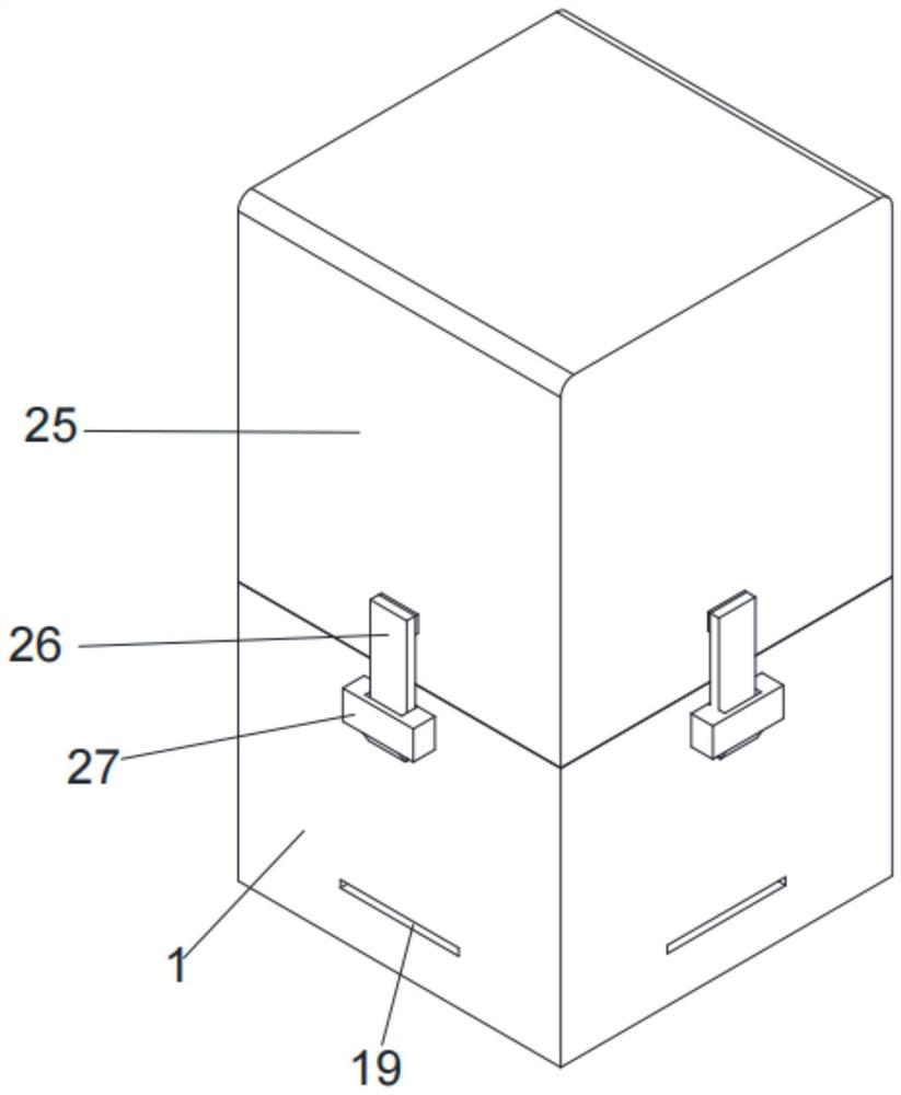
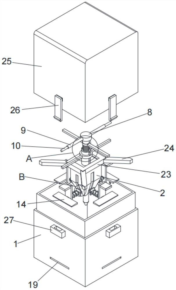
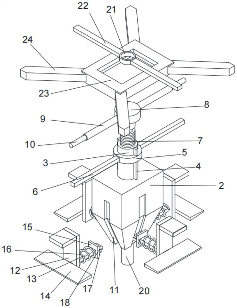
[0026] see Figure 1-Figure 5 , the present invention provides a technical solution, including a casing 1 and an upper cover 25, a counterweight 2 is arranged inside the casing 1, the upper end of the counterweight 2 is fixedly connected with a casing 1 3, and the upper end of the inner wall of the casing 3 is threaded A threaded rod 7 is connected, the outer wall of the sleeve 1 3 is fixedly connected to the limit plate 4, the sleeve 1 3 and the outer surface of the limit plate 4 are slidably sleeved with a sleeve ring 5, and the left and right ends of the sleeve ring 5 are fixed. A fixing rod 1 6 is connected, and the end of the fixing rod 1 6 away from the collar 1 5 is fixedly connected to the inner wall of the housing 1, the upper end of the circumferential side of the threaded rod 7 is provided with a clamping groove, and the inner wall of the clamping groove of the threaded rod 7 is rotated and sleeved with a collar. Two 21, the outer wall of the second ring 21 is fixed...

Embodiment 2

[0030] see figure 2 and image 3 , on the basis of the first embodiment, the present invention provides a technical solution: the lower end of the counterweight 2 is fixedly connected with an insertion rod 20, the lower end of the insertion rod 20 penetrates through the bottom plate of the sliding connection shell 1, and the inner lower end of the insertion rod 20 is provided with a Soil probe.

[0031] In this embodiment: when the counterweight block 2 moves down to improve the support, the insertion rod 20 moves down with the counterweight block 2 and is inserted into the soil through the bottom plate of the casing 1, the insertion rod 20 further improves the stability, and the lower end of the insertion rod 20 is inserted into the soil. The soil quality probe can be inserted into the soil to monitor the soil quality in real time, and transmit the data to the management personnel's equipment. When a geological disaster occurs, the soil quality changes, and the management p...


PUM


Abstract

The invention discloses a demarcation device for natural resource space planning, and relates to the technical field of environment planning, the demarcation device comprises a shell and an upper cover, a balancing weight is arranged in the shell, the upper end of the balancing weight is fixedly connected with a first sleeve, the upper end of the inner wall of the first sleeve is in threaded connection with a threaded rod, and the outer wall of the first sleeve is fixedly connected with a limiting plate; the outer surfaces of the first sleeve and the limiting plate are slidably sleeved with a first lantern ring, the left end and the right end of the first lantern ring are fixedly connected with first fixing rods, the ends, away from the first lantern ring, of the first fixing rods are fixedly connected with the inner wall of the shell, a clamping groove is formed in the upper end of the circumferential side face of the threaded rod, and the inner wall of the clamping groove of the threaded rod is rotatably sleeved with a second lantern ring. The outer wall of the second lantern ring is fixedly connected with a second fixing rod, and the technical problems that when geological disasters occur, soil below the boundary tablet can loosen to a certain degree, so that the boundary tablet loses the stable supporting and fixing effect, the boundary tablet is prone to laterally turning over to the ground, and the definite demarcation indication effect cannot be achieved are solved.

Description

technical field [0001] The invention relates to the technical field of environmental planning, in particular to a delimitation device for natural resource space planning. Background technique [0002] Natural resources refer to the substances in nature that humans can directly obtain for production and life. Natural resources are particularly important to the development of society and need to be protected and managed. When planning natural resources space, delimitation management is required. [0003] However, most of the existing boundary delimitation devices are simple boundary markers. The boundary markers are inserted into the soil for fixing. In the event of geological disasters, the soil under the boundary markers will loosen to a certain extent, which will cause the boundary markers to lose their stable supporting and fixing effect, making the boundary markers easy to side. Overturned, unable to play a clear demarcation indication effect. SUMMARY OF THE INVENTION ...

Claims


Application Information

Patent Timeline
IPC IPC(8): G09F7/00G09F7/18G01N33/24
CPCG09F7/00G09F7/18G01N33/24G09F2007/005G09F2007/1873Y02W30/10
Inventor 王翠翠尚晶
Owner 王翠翠
Why Eureka
Try Eureka