[0028] The technical solutions in the embodiments of the present invention will be clearly and completely described below with reference to the embodiments of the present invention. Obviously, the described embodiments are only a part of the embodiments of the present invention, rather than all the embodiments. Based on the embodiments of the present invention, all other embodiments obtained by those of ordinary skill in the art without creative efforts are all related to the protection scope of the present invention.
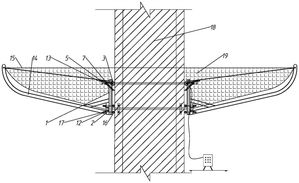
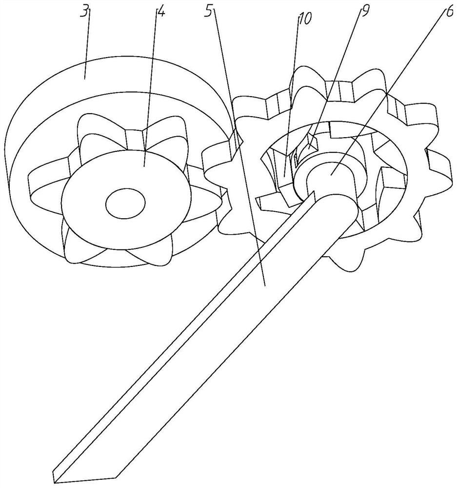
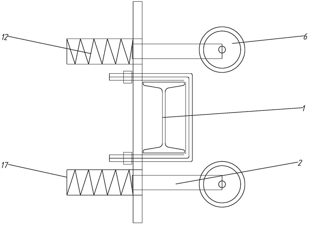
[0029] like Figure 1 to Figure 6 As shown in the figure, the present embodiment proposes a top-up type anti-falling device for high-altitude construction of bridge piers that can be lifted automatically, including an anti-falling mechanism, a driving mechanism and a locking mechanism. The support ring 1 on the support ring 1 and the anti-falling net 19 arranged on the support ring 1; the driving mechanism includes a plurality of driving wheels 3 that are rotated and arranged on the support ring 1, and the plurality of driving wheels 3 are fitted together The side wall of the bridge pier 18; the locking mechanism includes a brake lever 5 and a first spring 7, the brake lever 5 is hinged on the support ring 1 and the end abuts or disengages from the abutment of the bridge pier 18, the brake The free end of the rod 5 is inclined downward, the two ends of the first spring 7 are respectively arranged on the brake rod 5 and the support ring 1, and the first spring 7 provides the brake rod 5 close to the bridge pier 18. force.
[0030] In the present invention, the support ring 1 is formed by connecting support rods, the ends of adjacent support rods are connected by flanges, the adjacent support rods are connected by steel bars, the two ends of the steel bars are threaded, and the support rods are provided with through holes. After the steel bars pass through the through holes of the two adjacent support rods, tighten the nuts at both ends of the steel bars to fasten the corners of the support ring 1, increase the overall stiffness of the support rods, reduce structural deformation, and the overall shape of the support ring 1. The outline of the outer surface of the pier column is the same, and its size is slightly larger than that of the bridge pier 18. A protective net is installed on the support ring 1, and a driving wheel 3 is rotated on the support ring 1. A control electric box is set on the ground, and the control electric box provides the servo motor with electricity through the wire. Electric power, and control the working state of the servo motor, the servo motor drives the drive wheel 3 to move up or down; during the construction of the bridge piers, because the height of the working surface of the bridge pier 18 continues to rise, and the surface of the piers is generally free of attachments, the anti-fall net 19 cannot be set, and it is more difficult to change with the change of the position of the construction work surface of the bridge pier 18. The drive wheel 3 drives the support ring 1 to move on the bridge pier 18, which solves the problem that the position of the working surface on the bridge pier 18 is too high, and the anti-fall net 19 cannot be set. The automatic installation method saves a lot of time and saves time and effort when installing the anti-falling net 19; after the driving wheel 3 reaches a certain height, in order to prevent the anti-falling net 19 from slipping, a locking mechanism is added on the support ring 1 , the locking mechanism is composed of a brake lever 5, a rotating shaft 6 and a first spring 7, the rotating shaft 6 can rotate on the support ring 1, the end of the rotating shaft is provided with a brake lever 5, the free end of the brake lever 5 is inclined downward, and the brake lever 5 is inclined downward. A first spring 7 is connected between the moving rod 5 and the support ring 1. The first spring 7 will provide the force of the brake rod 5 to approach the bridge pier 18. When the support ring 1 reaches the designated position, the driving wheel 3 stops working, and the brake rod The end of 5 will push the bridge pier 18 tightly to prevent the support ring 1 from sliding down rapidly, which improves the safety of the equipment.
[0031] Further, it also includes,
[0032] The locking mechanism further includes a ring gear 8 , a rotating shaft 6 , a braking tooth 9 and a limit block 10 , the ring gear 8 is rotatably arranged on the support ring 1 , and the rotating shaft 6 is rotatably arranged on the support ring 1 . and located in the ring gear 8 , the brake lever 5 is arranged on the rotating shaft 6 , the side wall of the rotating shaft 6 has a groove 20 , and the braking teeth 9 are arranged in a radial direction along the rotating shaft 6 . In the groove 20, the upper end surface of the braking tooth 9 is an arc surface, a second spring 11 is arranged between the braking tooth 9 and the groove 20, and the outer wall of the ring gear 8 is provided with a wheel The drive wheel 3 is coaxially provided with a gear 4, and the inner ring of the ring gear 8 is provided with ratchet teeth. After the ratchet teeth rotate, the braking teeth 9 are toggled. 6. There is a gap between the side walls, the limit block 10 is arranged on the support ring 1, and the limit block 10 is located in the gap.
[0033] In this embodiment, the ring gear 8 is rotatably arranged on the support ring 1, the ring gear 8 and the rotating shaft 6 are coaxial, and the ring gear 8 is sleeved on the rotating shaft 6, the outer side wall of the ring gear 8 is provided with gear teeth, and the gear 4 is connected Ring gear 8 and gear 4, the inner side wall of ring gear 8 is provided with ratchet teeth, there is a gap between the end of the ratchet teeth and the rotating shaft 6, the braking tooth 9 slides in the groove 20 on the side wall of the rotating shaft 6, the second spring 11 The two ends are respectively connected with the bottom of the braking tooth 9 and the bottom wall of the groove 20. The second spring 11 pushes the braking tooth 9 to slide to the outside of the groove 20. There is also a limit block 10 on the support ring 1. The limit block 10 is located in the gap between the end of the ratchet teeth and the rotating shaft 6, and neither is in contact with the rotating shaft 6 and the ratchet teeth;
[0034]When the driving wheel 3 moves upward, the gear 4 on the rotating shaft 6 will drive the ring gear 8 to rotate by means of the chain. At this time, the arc edge on the ratchet tooth is in contact with the arc surface on the braking tooth 9, thereby pushing the braking tooth 9 to the concave. Sliding in the groove 20 will not drive the rotating shaft 6 to rotate at this time, and the locking mechanism is in a working state; when the driving wheel 3 moves downward, it will drive the ring gear 8 to reverse, and the ratchet teeth will move the brake teeth 9 at this time, and then Drive the rotating shaft 6 to rotate, and finally drive the brake lever 5 away from the bridge pier 18, and the locking mechanism fails, because the brake lever 5 cannot always follow the ring gear 8 to rotate, so when the brake lever 5 rotates to a certain angle, the brake tooth 9 will be in contact with the pier 18. When the limit block 10 contacts, the limit block 10 will squeeze the brake tooth 9 into the groove 20 along the arc surface of the brake tooth 9, so that the brake tooth 9 does not contact the ratchet teeth, and the cycle reciprocates; this design realizes The automation of the rise and fall of the support ring 1 facilitates the installation and disassembly of the anti-falling net 19, and greatly reduces the time for installing and disassembling the anti-falling net 19; when the support ring 1 descends, the driving mechanism is damaged, the driving wheel 3 and the pier column The friction force between them disappears, the deceleration effect of the driving wheel 3 will disappear, and the descending speed of the support ring 1 will not be controlled, because the driving wheel 3 will no longer provide driving force for the ring gear 8 at this time, so the brake lever 5 will be in Under the action of the second spring 11, it moves to the bridge pier 18, and the locking device is activated, so that the system can be safely fixed on the bridge pier 18 to prevent the occurrence of safety accidents.
[0035] Further, it also includes,
[0036] The driving mechanism further includes a hydraulic cylinder 13 , the hydraulic cylinder 13 is arranged on the support ring 1 , and the telescopic end of the hydraulic cylinder 13 is connected to the core shaft of the driving wheel 3 .
[0037] In this embodiment, the hydraulic cylinder 13 will make the driving wheel 3 tightly press the bridge pier 18, increase the friction force between the driving wheel 3 and the bridge pier 18, and facilitate the upward movement of the driving wheel 3; Prevent the support ring 1 from falling too fast, thereby causing the support ring 1 to be damaged.
[0038] Further, it also includes,
[0039] The support ring 1 is evenly provided with a plurality of cantilever parts 14 , the cantilever parts 14 are arc-shaped and the ends are upturned, and the ends of the plurality of cantilever parts 14 are connected by means of a pulling rope 15 . The drop net 19 is fixed on the drawstring 15 by means of tendons.
[0040] In this embodiment, the cantilever 14 is evenly installed on the outer side of the support ring 1 , the cantilever 14 is arc-shaped and the ends are raised upward, so that the cantilever 14 surrounds a bowl-shaped structure on the outside of the support ring 1 , The ends of the cantilever 14 are connected by means of a pull rope 15, and the anti-falling net 19 is fixed on the pull rope 15 by means of a rib rope; The bowl-shaped structure can better accommodate people who fall on the protective net and prevent people from accidentally falling from the edge.
[0041] Further, it also includes,
[0042] The pulling rope 15 is connected to the end of the suspension member 14 by means of a buckle.
[0043] In this embodiment, the pull rope 15 is connected with the suspension member 14 through a buckle, so that the pull rope 15 can be easily and quickly installed or disassembled, and the work efficiency is improved.
[0044] Further, it also includes,
[0045] The height of the end of the anti-fall net 19 close to the bridge pier 18 is lower than that of the end away from the bridge pier 18 .
[0046] In this embodiment, after the anti-falling net 19 is installed, a funnel-shaped structure with a free edge close to the pier 18 lower than the free edge away from the bridge pier 18 is formed, which can prevent falling persons from popping out and improve the safety of the equipment.
[0047] Further, it also includes,
[0048] The positioning mechanism includes a positioning wheel 16, a sleeve 17, a telescopic rod 2, and a third spring 12. The telescopic rod 2 is slidably arranged in the sleeve 17, and both ends of the third spring 12 are respectively connected to the telescopic rod 12. The rod 2 is connected to the bottom wall of the tube sleeve 17, and the end of the telescopic rod 2 is rotated with a positioning wheel 16, the positioning wheel 16 is in contact with the side wall of the bridge pier 18, and the third spring 12 provides the telescopic rod 2. The force close to the bridge pier 18, the sleeve 17 is arranged on the support ring 1.
[0049] In this embodiment, the third spring 12 provides the force of the telescopic rod 2 to approach the bridge pier 18, and further provides the force of the positioning wheel 16 to approach the bridge pier 18, so that the positioning wheel 16 is close to the side wall of the bridge pier 18, and the positioning mechanism can make the support ring 1 in a certain It can prevent the system from shaking too much under the action of wind load and improve the stability of the support ring 1.
[0050] The above are only preferred embodiments of the present invention and are not intended to limit the present invention. Any modification, equivalent replacement, improvement, etc. made within the spirit and principle of the present invention shall be included in the protection scope of the present invention. within.