Dust removal power distribution cabinet and use method thereof
A technology for power distribution cabinets and electric cabinets, which is applied in substation/power distribution device shells, electrical components, substation/switch layout details, etc., which can solve the problems of dust flying and dust falling inside the power distribution cabinet, and simplify the installation process , easy installation or disassembly, and the effect of improving the degree of automation
- Summary
- Abstract
- Description
- Claims
- Application Information
AI Technical Summary
Problems solved by technology
Method used
Image
Examples
Embodiment 1
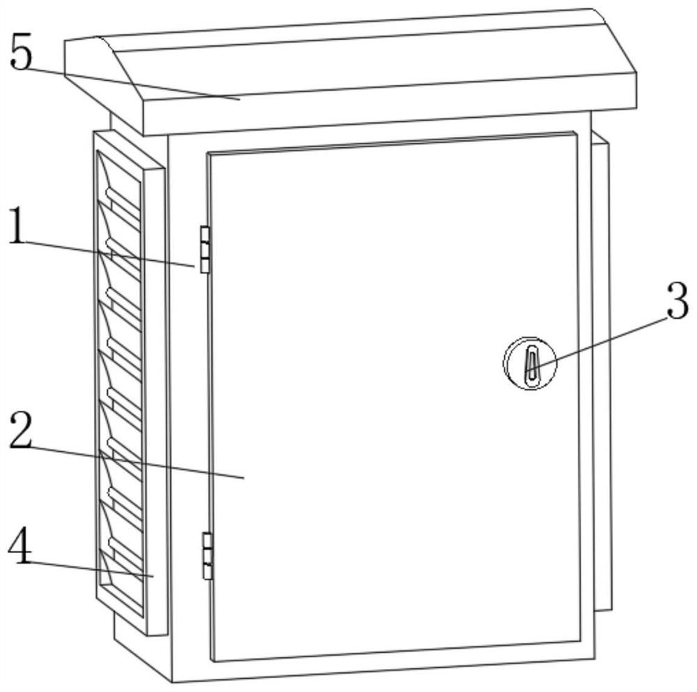
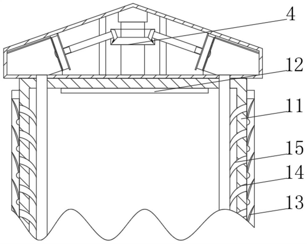
[0034] see Figure 1-2 , the present invention provides a technical solution: a dust removal power distribution cabinet and a method of using the same, comprising a power distribution cabinet main body 1, one side of the power distribution cabinet main body 1 is pivotally connected to an electric cabinet door 2 through a hinge, and the electric cabinet door 2 is far away from One side of the power distribution cabinet main body 1 is provided with a door lock 3, both sides of the power distribution cabinet main body 1 are fixedly connected with a fixing frame 4, the top of the power distribution cabinet main body 1 is provided with a power cabinet dust removal cover 5, and the power distribution cabinet main body 1 It includes an electric cabinet shell 11, the top of the inner wall of the electric cabinet shell 11 is fixedly connected with a temperature sensing resistor 12, the sides of the electric cabinet shell 11 close to the fixing frame 4 are provided with filter blades 13,...
Embodiment 2
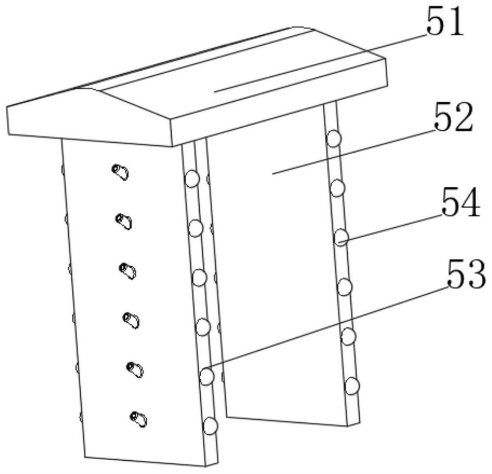
[0037] see Figure 2-4, the present invention provides a technical solution on the basis of the first embodiment: a dust removal power distribution cabinet and a method of use thereof, the dust removal cover 5 of the power cabinet includes a top cover 51, and both sides of the bottom side of the top cover 51 are connected with an air intake filter Mechanism 52, both sides of the air intake filter mechanism 52 are provided with sliding holes 53, and the bottom of the inner wall of the sliding hole 53 is fixedly connected with a fixing block 54 through a spring. The cover 51 includes a connecting shell a1, and the inner wall side of the connecting shell a1 is fixedly connected with a fixed partition a2 and a moving rod a3, and the connecting block of the moving rod a3 is rotatably connected with a stretching rod a4, and the stretching rod a4 is away from the moving rod a3. One end is rotatably connected with the moving plate a5 through the rotating seat, the side of the moving p...
Embodiment 3
[0040] see Figure 2-6 , the present invention provides a technical solution on the basis of the second embodiment: a dust removal power distribution cabinet and a method of using the same. The air intake filter mechanism 52 communicates with the air intake filter mechanism 52 and includes a fixed casing b1, one side of the fixed casing b1 is connected with an intake pipe b2, and one end of the intake pipe b2 away from the inner wall of the fixed casing b1 is rotatably connected by a rotating shaft. There is an air intake plate b3, a connecting spring b4 is fixedly connected to one side of the air intake plate b3, a filter screen b5 is fixedly connected to the middle of the inner wall of the air intake duct b2, and the side of the fixed housing b1 away from the air intake duct b2 is provided with an air outlet Slot b6, one side of the inner wall of the air outlet groove b6 is connected with an air outlet plate b7 through a rotating pin, and the side of the fixed housing b1 clo...
PUM
 Abstract
Description
Claims
Application Information
 - R&D
- Intellectual Property
- Life Sciences
- Materials
- Tech Scout
- Unparalleled Data Quality
- Higher Quality Content
- 60% Fewer Hallucinations
Browse by: Latest US Patents, China's latest patents, Technical Efficacy Thesaurus, Application Domain, Technology Topic, Popular Technical Reports.
© 2025 PatSnap. All rights reserved.Legal|Privacy policy|Modern Slavery Act Transparency Statement|Sitemap|About US| Contact US: help@patsnap.com


