Antenna element

An antenna element and antenna technology, applied in the direction of antenna, antenna parts, electrical components, etc., can solve the problems that the antenna cannot be used as a magnetic current antenna, and the reception performance is deteriorated

Inactive Publication Date: 2004-07-14
PANASONIC CORP
View PDF0 Cites 0 Cited by
  • Summary
  • Abstract
  • Description
  • Claims
  • Application Information

AI Technical Summary

Problems solved by technology

The disadvantage is that since a large amount of current flows not only on the antenna but also on the main board of the wireless device, the θ component, that is, the current component is dominant, and the antenna can hardly function as a magnetic current type antenna
As a result, there is an i...

Method used


Image

  • Antenna element
  • Antenna element
  • Antenna element

Examples


Embodiment Construction

[0022] (first embodiment)

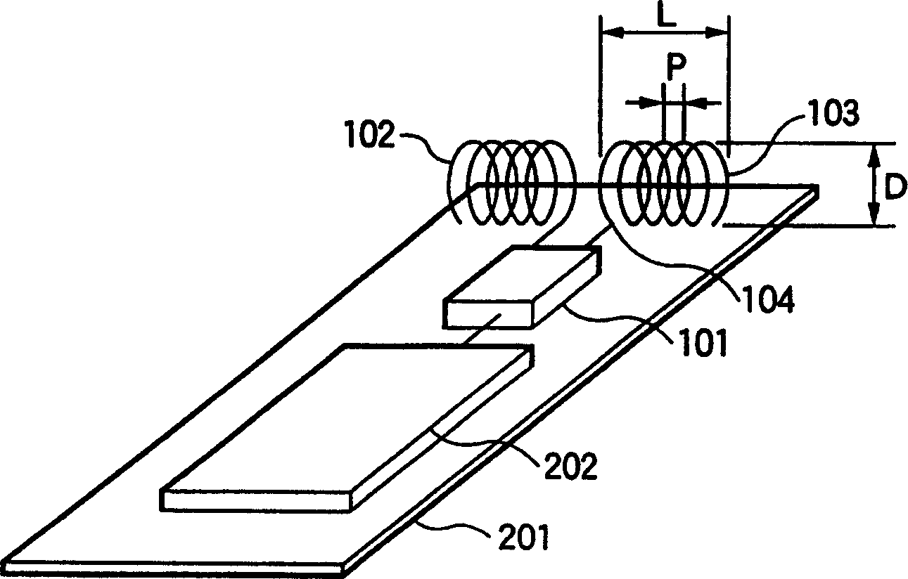
[0023] like figure 1 As shown, the antenna element according to the first embodiment of the present invention includes a pair of helical antenna elements 102,103. These antenna parts 102 and 103 are connected via a balun 101 to a radio circuit (radio circuit) 202 provided on a main board 201 of the wireless device. The connection between the balun 101 and the helical antenna parts 102 , 103 is realized by a balanced feeder 104 . The balun 101 is provided to interconnect the feeder 104 of the unbalanced system with the feeder 104 of the balanced system when the wireless loop 202 is connected to the unbalanced system. If the output of the wireless loop 202 consists from the start of a balanced system, the helical antenna elements 102, 103 can be directly connected to the wireless loop 202 via the feeder 104 without being interconnected via the balun 101.

[0024] The paired first helical antenna part 102 and the second helical antenna part 103 are...


PUM


Abstract

An antenna unit adapted to be incorporated inside a main body of a mobile radio set. A pair of helical antenna elements (102), (103) are connected to a balanced feeding line (104). The helical antenna elements have antenna axes parallel to a base plate (201) of the radio set and being arranged in proximity to the base plate of the radio set at a sufficiently small distance as compared with their wavelength. By conducting a balanced power supply to the helical antenna elements, an earthed electric current component flowing on the base plate of the radio set can be reduced, thus decreasing influence of a user's body when the radio set is operated in the user's hand. Additionally, the antenna can possess radiation characteristics of both an electric current type antenna and a magnetic current type antenna, and therefore, the receiving performance when the radio set is tilted in use can be enhanced.

Description

technical field [0001] The present invention relates to an antenna element mainly used in small mobile wireless devices, and more particularly, to an antenna element which can obtain excellent radiation characteristics even when it is used close to a human body. Background technique [0002] Recently, the demand for mobile communication devices such as mobile phones has risen sharply, and a compact, light and thin wireless device is pursued. [0003] As a conventional antenna for a mobile phone, a fixed type helical antenna, a planer inverted antenna, etc. are commonly used, and an antenna having good portability and compactness in comparison to it has been realized. A small-sized antenna system that does not cause inconvenience when used with wireless devices. [0004] Figure 5 This is an outline drawing of a fixed helical antenna widely used as a general-purpose antenna for mobile phones. The fixed type helical antenna element 10 is provided on the main body 11 of the m...

Claims


Application Information

Patent Timeline
IPC IPC(8): H01Q1/48H01Q1/24H01Q1/36H01Q9/16H01Q9/26H01Q9/28H01Q11/08
CPCH01Q9/16H01Q9/28H01Q9/26H01Q1/243H01Q11/08H01Q1/36
Inventor 小柳芳雄森下久藤本京平
Owner PANASONIC CORP
Why Eureka
Try Eureka