Mouthpiece

A technology of braces and veneers, applied in dentistry, orthodontics, prosthetics, etc., can solve the problems of heavy workload and high treatment costs for dentists

Inactive Publication Date: 2004-09-15
上西雅一
View PDF1 Cites 1 Cited by
  • Summary
  • Abstract
  • Description
  • Claims
  • Application Information

AI Technical Summary

Problems solved by technology

For this reason, it takes about 1-2 hours to properly adjust the treatment time once, and the workload of the dentist is heavy, and the treatment cost is high.

Method used


Image

  • Mouthpiece
  • Mouthpiece
  • Mouthpiece

Examples


Embodiment Construction

[0036] Embodiments of the present invention will be described below with reference to the accompanying drawings.

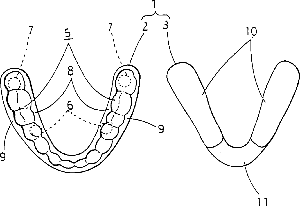
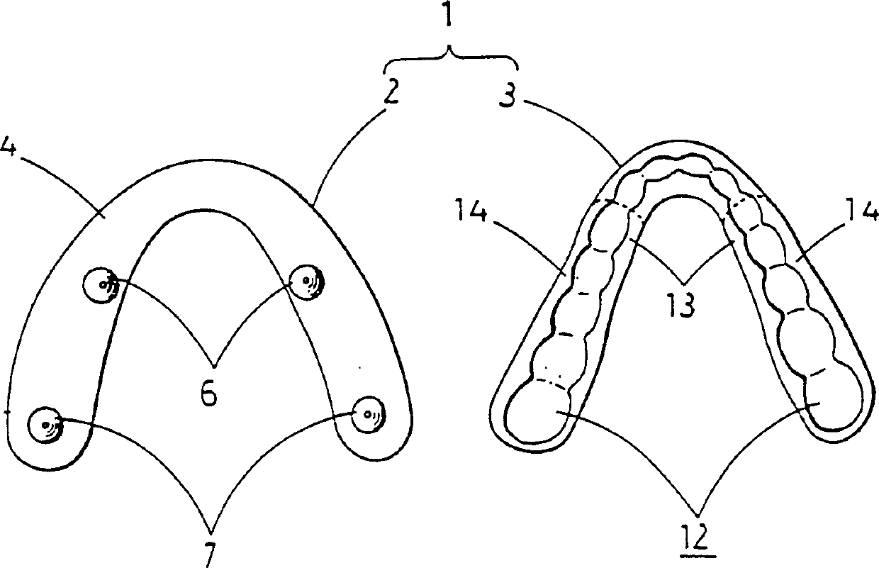
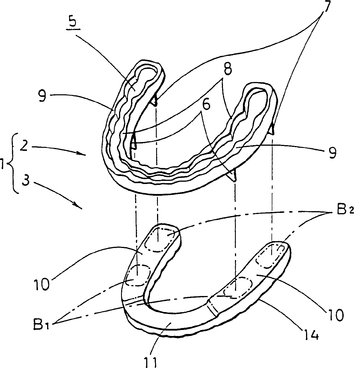
[0037] FIG. 1 is a plan view showing a mouthpiece according to an embodiment of the present invention, FIG. 2 is a bottom view, FIG. 3 is a perspective view, and FIG. 4 is a front view.

[0038] In each figure, the dental mouthpiece 1 of this embodiment is composed of an upper cover sheet 2 covering the maxillary side dentition and a lower cover sheet 3 for covering the lower jaw side dentition used up and down with respect to the upper cover sheet 2 . These upper mantle 2 and lower mantle 3 are made of, for example, dental methyl methacrylate resin, and are formed substantially in a horseshoe shape in plan view to be fitted to all upper and lower teeth.

[0039] On the opposite surface (bottom surface) 4 of the upper cover sheet 2, four cone-shaped protrusions 6, 6, 7, 7 protruding towards the lower cover sheet 3 are set, and on the upper cover sheet 2 to surroun...


PUM


Abstract

A mouthpiece which has a simple structure, is therefore easy to machine for adjustment, and is extremely inexpensive. The mouthpiece comprises an upper piece to be fitted to the upper jaw dentition, and a lower piece vertically opposed to the upper piece and to be fitted to the lower jaw dentition. Projections are provided on the opposed surface of one of the upper and lower pieces and project toward the other piece, and a supporting surface for supporting the projections when it comes in contact therewith. An upper dentition fitting groove for fitting the upper piece to the upper-jaw dentition is formed in the upper surface of the upper piece, and a lower dentition fitting groove for fitting the lower piece to the lower-jaw dentition is formed in the lower surface of the lower piece.

Description

technical field [0001] The present invention relates to a mouthpiece for correcting the posture of the whole body by elongating the muscles supporting the lower jaw equally from left to right by occlusal lifting. Background technique [0002] Fig. 17(a) and Fig. 17(b) show the general upper jaw, lower jaw, and their adjacent bones. [0003] Fig. 17(a) shows the state of occlusal upper and lower dentition. As shown in FIG. 17( a ), the skull is supported on the first cervical vertebra 25 at the upper end of the spine, and the maxillary dentition 22 grows on the upper jaw 20 at the front of the skull. The mandible 21 having the mandibular dentition 23 is complexly supported by the masseter muscle and various muscles. It is preferable for a person to take a natural head posture so that the occlusal surface indicated by the axis X matches the ideal occlusal surface (a substantially horizontal surface), and the axis Y perpendicular to the axis X is vertical. [0004] In this w...

Claims


Application Information

Patent Timeline
Patent Type & Authority Patents(China)
IPC IPC(8): A61C7/08
CPCA61C7/08Y10S602/902
Inventor 上西雅一
Owner 上西雅一
Why Eureka
Try Eureka