Flap wheel

A fin grinding wheel and fin technology are applied in the field of grinding the geometry of fins to achieve the effects of good grinding performance, good processing and cost reduction

Inactive Publication Date: 2009-11-11
RHODIUS SCHLEIFWERKZEUGE
View PDF2 Cites 2 Cited by
  • Summary
  • Abstract
  • Description
  • Claims
  • Application Information

AI Technical Summary

Problems solved by technology

But since the inside edge is concave, it has the disadvantage that the disc support is fitted automatically by these grinding fins

Method used


Image

  • Flap wheel
  • Flap wheel
  • Flap wheel

Examples


Embodiment Construction

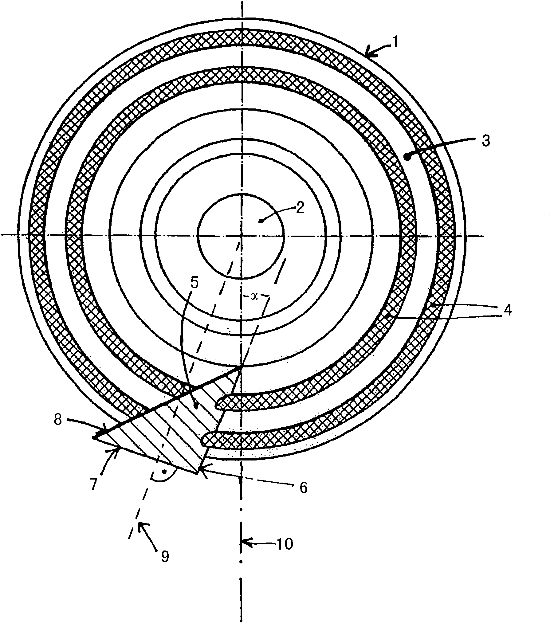
[0025] figure 1Shown is a disc-shaped support 1 made of synthetic material (Kunststoff) with a standard hole 2 formed in the center of the support 1 . This standard hole is suitable for inserting a fastening element for fastening a processing spindle of a processing machine. Even though any disc shape and size could be considered, the support used in this case had a diameter of 115 mm. Instead of synthetic materials, fibrous materials, wood or metal can also be used. The bearing 1 comprises an annular bearing section 3 , which is inclined conically towards the outside, and which is centered on the axis. The cone angle in this example is about 12°. Depending on the circumstances, angles between 10° and 30° can also be used. During processing, two concentric sausages 4 of adhesive material can be provided on the support section 3 , by means of which sausages 4 the individual grinding fins are bonded. The automatic setting of the sausage 4 is known, for example, in a first ...


PUM


Abstract

The invention relates to a flap wheel, comprising a plate-shaped carrier, which can be rotatably driven about an axis and carries a plurality of abrasive flaps overlapping in a tile-like manner, wherein the abrasive flaps are fastened to a circular carrier section centered on the axis, particularly by means of gluing, wherein the abrasive flaps have a straight first edge, the lower edge, and a second straight edge abutting thereon, the outer edge, and wherein the abrasive flaps have a third edge, the inner edge, which cuts both the lower edge and the outer edge at least in the extension of the flap, wherein the outer edges of the abrasive flaps form the outer contour of the flap wheel. The invention also relates to a method for producing the same.

Description

technical field [0001] The invention relates firstly to the geometry of a grinding wing, which is arranged, in particular adhesively, on a rotatably drivable grinding wheel, wherein the grinding wing has a straight first side and is aligned with the second side. A second straight side adjacent to one side. The invention also relates to a grinding foil wheel having a disk-shaped support which is drivably rotatable about an axis and supports a plurality of such grinding foils which overlap in a shoe-like manner. Furthermore, the grinding fins are fastened, in particular glued, to an annular support section centered on said axis. The invention also relates to a method for producing such a flap grinding wheel. Background technique [0002] Various embodiments of such flap grinding wheels are known. Patent document DE 295 10 727 U1, for example, describes a grinding disc to which a ring-shaped coating formed of a plurality of individual grinding fins is bonded to the support s...

Claims


Application Information

Patent Timeline
IPC IPC(8): B24D13/16
CPCB24D13/16
Inventor 彼得·德根
Owner RHODIUS SCHLEIFWERKZEUGE
Why Eureka
Try Eureka