Tyre with laced breaker by reinforcement

A technology of reinforcing parts and reinforcing elements, applied to special tires, tire parts, reinforcing layers of pneumatic tires, etc., can solve problems such as limited durability

Inactive Publication Date: 2004-09-22
MICHELIN & CO CIE GEN DES ESTAB MICHELIN
View PDF3 Cites 2 Cited by
  • Summary
  • Abstract
  • Description
  • Claims
  • Application Information

AI Technical Summary

Problems solved by technology

The tires disclosed in this patent have limited durability, especially in the case of motor vehicles carrying heavy loads

Method used


Image

  • Tyre with laced breaker by reinforcement
  • Tyre with laced breaker by reinforcement
  • Tyre with laced breaker by reinforcement

Examples


Embodiment Construction

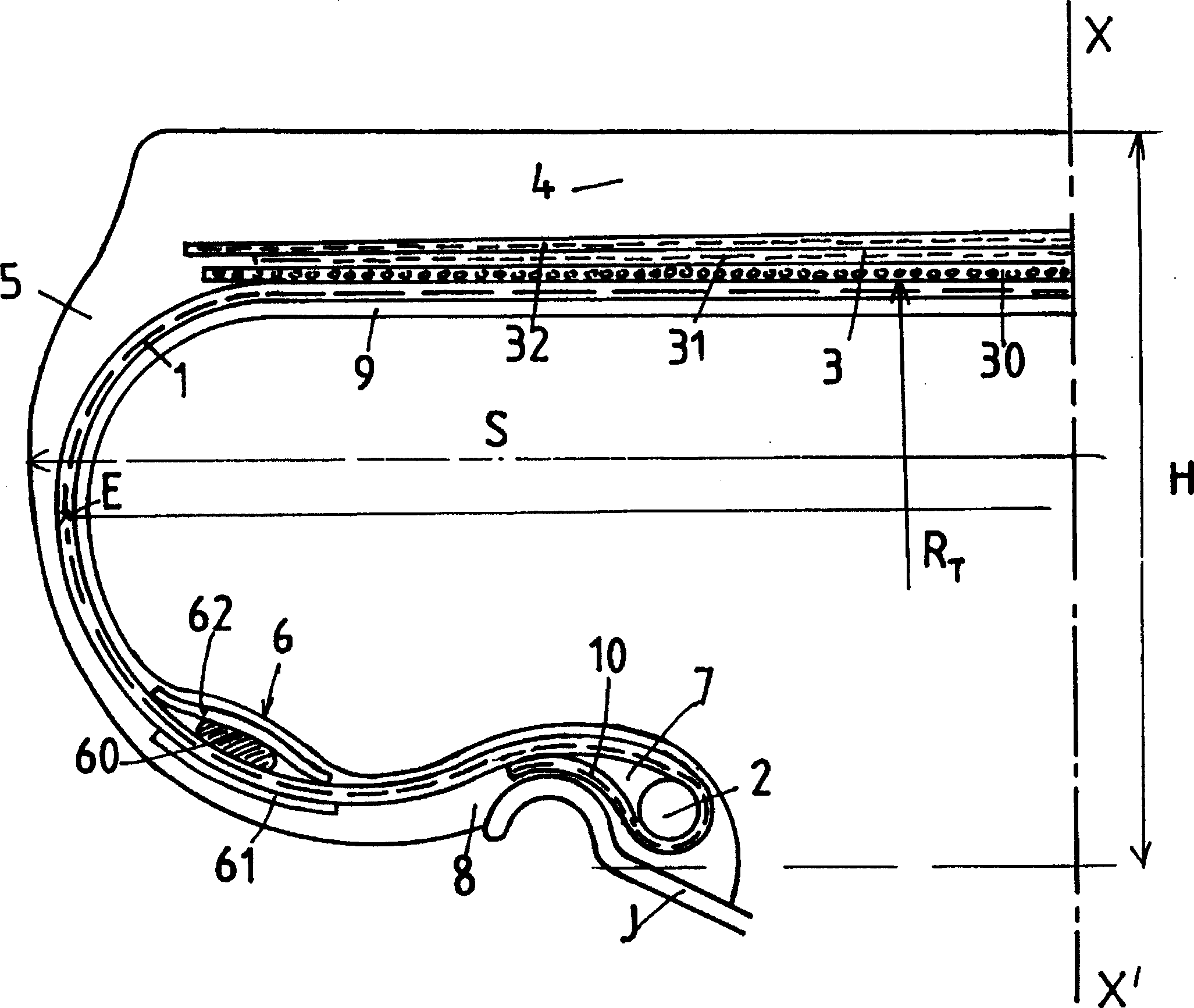
[0031] figure 1 The tire P has a build ratio H / S equal to 0.55 and is mounted on a rim J called a 9×22.5 rim. The carcass reinforcement 1 is formed by a single ply of reinforcing elements being cables made of aramid. Said ply 1 is anchored in each bead B to a braided bead wire 2 and has a portion ( 10 ) folded over itself whose meridian profile surrounds the hook representing the rim J The arc of the circular portion of the edge. Said turned-up portion 10 is separated from the main portion 1 of the carcass ply by a triangular small part 7 . Between the point E of maximum axial width of the carcass ply and the bead wire B is arranged a reinforcing layer 6 which in this case comprises a non-conductive A ply 61 of stretched metal cables, a ply 62 of inextensible metal cables located radially outside the carcass ply 1 and a reinforcing ring 60 between said ply 1 and the ply 62, the reinforcing ring consisting of a Formed from turns of wire, the wire gives the ring an almost pe...


PUM


Abstract

A tire with a form ratio H / S between 0.3 and 0.8 has a carcass reinforcement (1) which is covered radially by a quasi-cylindrical crown reinforcement (3) and which is tangential at T to a holding circle C. The common tangent at T to the circle C and to the meridian profile of the carcass (1) makes an angle alpha of between +20° and -80° with respect to a line parallel to the rotation axis and passing through the tangency point T. In its portion located between the tangency point T and the point E of greatest axial width, the carcass reinforcement (1) is provided with a reinforcement armature (6) of circumferentially non-extensible elements. Viewed in meridian cross-section and when the tire is fitted and inflated to the recommended pressure, the carcass (1) has a meridian profile consisting of four circular arcs configured to improve the endurance of the tire while improving its rolling resistance.

Description

technical field [0001] The present invention relates to a tire with radial carcass reinforcement, and more particularly to a tire intended to be mounted on a motor vehicle, such as a truck, tractor, trailer or passenger car, carrying a heavy load and traveling at a sustained speed. Background technique [0002] "Heavy duty" tires generally comprise a radial carcass reinforcement consisting of a single ply of metallic reinforcing elements anchored in each bead to at least one bead wire. Said carcass reinforcement is radially covered by a crown reinforcement consisting of at least two working plies made of inextensible metal reinforcing elements, the reinforcing elements being in each ply They are parallel to each other and cross from one ply to the other, forming an angle between 10° and 45° with the tire circumferential direction. Said working ply is usually a so-called protective ply made of extensible metal reinforcing elements and a so-called triangular mesh ply made of ...

Claims


Application Information

Patent Timeline
IPC IPC(8): B60C3/00B60C3/04B60C9/08B60C9/20B60C15/00B60C15/02B60C15/06
CPCB60C3/04B60C15/0203B60C13/009B60C3/00B60C9/0292Y10T152/10864Y10T152/10855Y10T152/10828Y10T152/10819B60C9/00
Inventor 若泽·梅里诺·洛佩斯帕斯卡尔·奥塞尔
Owner MICHELIN & CO CIE GEN DES ESTAB MICHELIN
Why Eureka
Try Eureka