Electromagnetic relay

A technology of electromagnetic relays and magnetic poles, applied in the direction of electromagnetic relays, relays, detailed information of electromagnetic relays, etc., can solve problems such as poor contact

Inactive Publication Date: 2004-09-22
MATSUSHITA ELECTRIC WORKS LTD
View PDF0 Cites 3 Cited by
  • Summary
  • Abstract
  • Description
  • Claims
  • Application Information

AI Technical Summary

Problems solved by technology

Correspondingly, when the switch T is located with the wall R 1 When in contact with the wall portion of the case R, the switch T and the wall portion R of the case R 1 Friction is genera

Method used


Image

  • Electromagnetic relay
  • Electromagnetic relay
  • Electromagnetic relay

Examples


Embodiment Construction

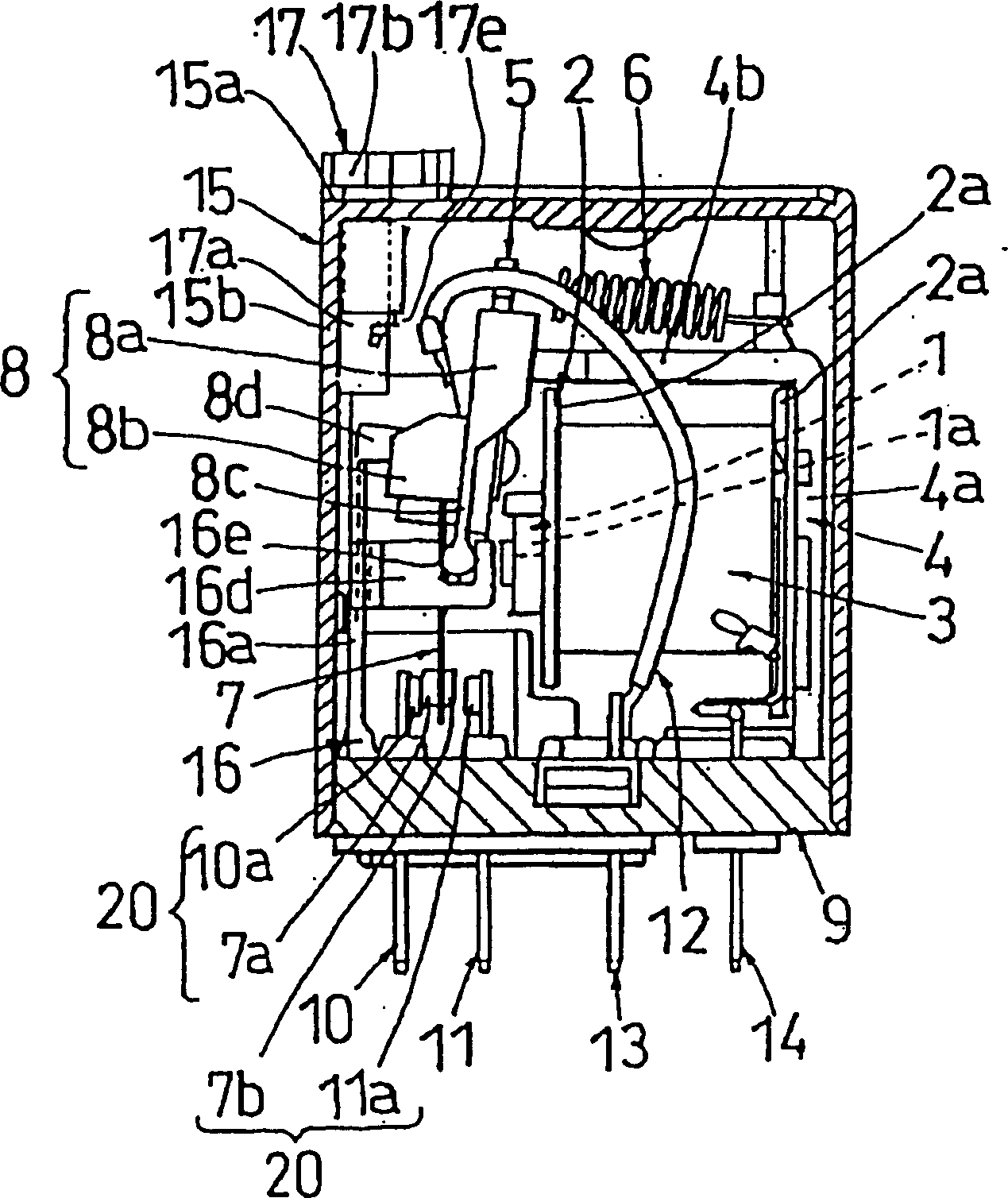
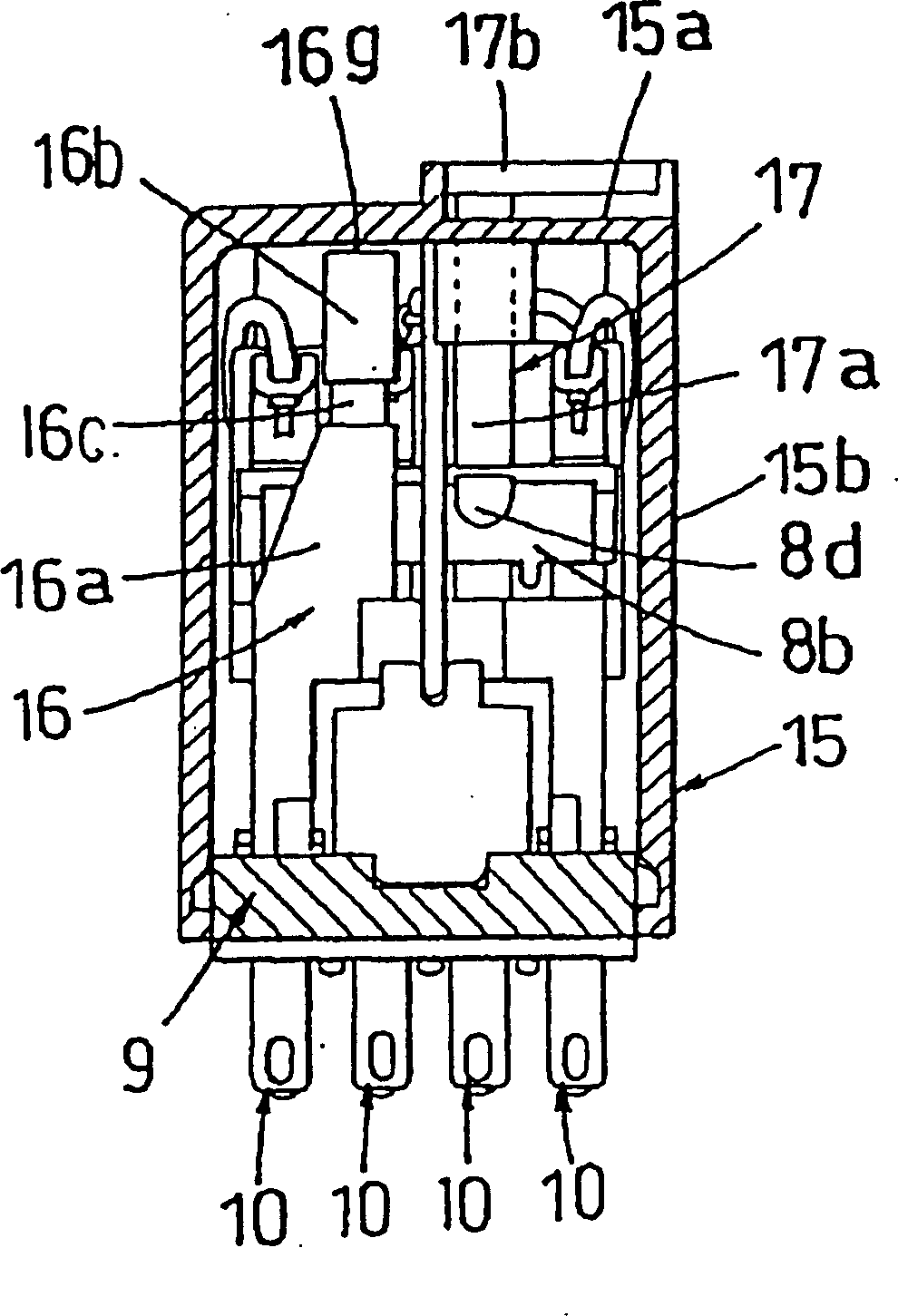
[0059] refer to Figure 1 to Figure 9 , the first embodiment of the present invention will be described. The structure of this electromagnetic relay includes: iron core 1; coil winding shaft 2; coil 3; yoke 4; armature 5; return spring 6; moving spring 7; moving part 8; substrate 9; contact terminal 11; lead wire 12; common terminal 13; coil terminal 14; case 15; display member 16;

[0060] The iron core 1 is formed of a magnetic material into a substantially round bar shape. The coil bobbin 2 is made of a molding material such as plastic, has a substantially columnar shape, and has a color 2a at both ends of a drum portion on which a coil 3 is wound. Next, the iron core 1 is inserted into the through hole in the drum portion of the coil bobbin 2 with one end protruding from the opening portion of the through hole. That is, the coil 3 is wound on the iron core 1 by the coil bobbin 2, and as a result, one end portion of the iron core 1 is formed as the magnetic pole portion ...


PUM


Abstract

An electromagnetic relay having: an iron core around which a coil is wound and on which a magnetic pole portion is provided; an armature which is attracted to and separated from the magnetic pole portion 1a of the iron core and driven; a contact point portion which comes into contact with and is separated from its partner, when the armature is driven; and a switch in which an operation portion which can be pressed so that the contact point portion comes into contact with and is separated from its partner, when the armature is not driven, is extended to the direction which is intersected with the pressing direction; and a case having an opposing portion opposite to the operation portion, the electromagnetic relay is structured such that, in at least either one of the operation portion or the opposing portion, the contact portion which can come into contact with the other when the operation portion is not pressed, is protruded toward the other.

Description

technical field [0001] The present invention relates to an electromagnetic relay in which a switch is provided which operates to bring contact portions into contact and abutment portions to separate when the armature is not energized. Background technique [0002] Usually, Figure 17 and Figure 18 Shown in is an electromagnetic relay with this structure. The structure of this electromagnetic relay includes: core A; coil winding shaft B; coil C; yoke D; armature E; return spring F; moving spring G; moving part H; substrate J; normally closed side contact terminal K; contact terminal L; lead wire M; common terminal P; coil terminal Q; display member S; [0003] The iron core A is formed of a magnetic material into a round bar shape. The coil bobbin B is formed into a substantially columnar shape by a molding material such as plastic, with flange portions B on both ends of the drum portion 1 , Wind the coil C around the drum part. Next, the iron core A is inserted into th...

Claims


Application Information

Patent Timeline
IPC IPC(8): H01H50/00H01H50/08H01H50/32H01H51/06
CPCH01H50/326
Inventor 大石晃元山正德
Owner MATSUSHITA ELECTRIC WORKS LTD
Why Eureka
Try Eureka