Trigger control device and method

A trigger control and trigger signal technology, which is applied in the direction of electrical program control, program control in sequence/logic controller, signal transmission system, etc., can solve frequent plug-in and exchange, trigger failure of trigger control device and data collection host, Reduce the penetration rate and other problems, achieve the best waterproof and dustproof effect, stable poor contact, and less susceptible to interference

Inactive Publication Date: 2011-03-30
ASKEY COMP
View PDF0 Cites 0 Cited by
  • Summary
  • Abstract
  • Description
  • Claims
  • Application Information

AI Technical Summary

Problems solved by technology

[0006] However, because the data collection host on the trigger controller often needs to be plugged and exchanged frequently due to different occasions or different functional requirements
This kind of frequent plugging and unplugging is required in the infrared communication method. The transparent window used to receive infrared rays is prone to wear and tear due to the frequent plugging and unplugging between the trigger controller and the data collection host, thereby reducing the penetration rate and causing trigger failure or triggering. bad question
[0007] Another prior art uses magnetic induction for triggering. Although it can avoid the existing problem of poor contact between the infrared communication method and the communication wiring, it is easily affected by the use environment due to the use of magnetic induction, resulting in a data collection host. The sensing fails or the data collection host generates wrong execution actions
[0008] Therefore, how to solve the problem of trigger failure between the trigger control device and the data collection host in the prior art will be what the present invention actively provides

Method used


Image

  • Trigger control device and method
  • Trigger control device and method
  • Trigger control device and method

Examples


Embodiment Construction

[0034] In order to fully understand the purpose, features and effects of the present invention, the present invention will be described in detail by means of the following specific embodiments and accompanying drawings, as follows:

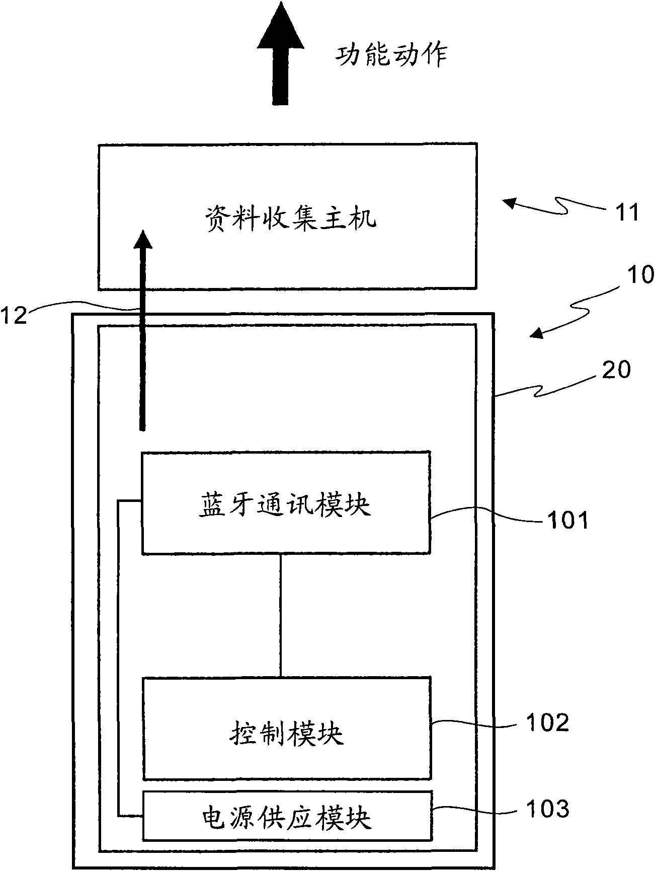
[0035] figure 1 A functional block diagram of an embodiment for controlling a data collection host using the present invention. The trigger control device of the present invention is used to activate a data collection host combined with it, so that the data collection host executes a corresponding functional action. As shown in the figure, a trigger control device 10 is used to trigger a data collection host 11 to execute a corresponding function. The trigger control device 10 at least includes: a Bluetooth communication module 101 , a control module 102 , a power supply module 103 and a casing 20 for accommodating the aforementioned components. Wherein, the control module 102 is electrically connected to the Bluetooth communication module 101 ,...


PUM


Abstract

The invention provides a trigger control device and a trigger control method. The trigger control device is used for starting a combined data acquisition host to execute the corresponding functional action; the trigger control device comprises a Bluetooth communication module, a control module, a power supply module and a shell for accommodating the previous components; the Bluetooth communication module establishes a connection between the trigger control module and the data acquisition host; and the control module controls the Bluetooth communication module to send a trigger signal so that the data acquisition host receives the trigger signal and is started. Therefore, the trigger control device starts the data acquisition host in a Bluetooth communication mode which is not easily disturbed so as to solve the problem of trigger failure caused by poor contact or disturbance susceptibility in the prior art.

Description

technical field [0001] The present invention relates to a trigger control technology, in particular to a device and method for trigger control of a data collection host using bluetooth communication. Background technique [0002] The data collection host is a device used to capture various data, and is often assembled with a trigger controller. The more common data collection hosts include code readers or inventory machines. The trigger controller is mainly to facilitate personnel to operate data Collect the functions of the host. Wherein, the barcode reader is a tool for reading barcodes. For example, when reading the barcode number 1234, the barcode reader will receive digital data representing 1234. In addition, the functions of the inventory machine and the barcode reader are similar, and usually have built-in operating software and storage media. When performing data collection, the data can be placed in the storage medium for calculation and management, and then impo...

Claims


Application Information

Patent Timeline
Patent Type & Authority Applications(China)
IPC IPC(8): G05B19/04G08C17/02
Inventor 张庭霖谢青峰
Owner ASKEY COMP
Why Eureka
Try Eureka