Pictrue signal shffling device and method
An image signal and shuffling technology, applied in image communication, digital video signal modification, pulse modulated TV signal transmission and other directions, can solve the problems of high redundancy of two compressed streams and complex encoding devices.
- Summary
- Abstract
- Description
- Claims
- Application Information
AI Technical Summary
Problems solved by technology
Method used
Image

Examples
Embodiment 1
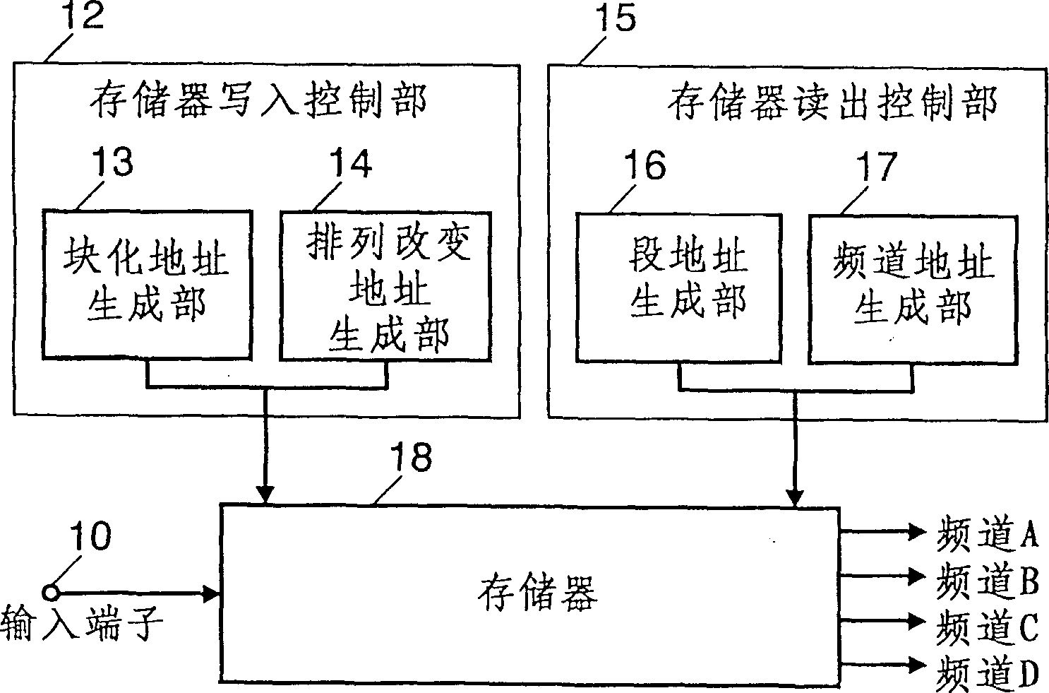
[0109] figure 1 is a block diagram of an image signal shuffling device according to Embodiment 1 of the present invention.
[0110] exist figure 1 In this case, the digital image signal input from the input terminal 10 is input to the memory 18 .
[0111] The block address generation unit 13 generates addresses for dividing input data into blocks on the memory. The arrangement change address generation unit 14 generates addresses for changing the arrangement of blocks on the memory.
[0112] The memory write control unit 12 controls the block address generation unit 13 and the arrangement change address generation unit 14 to calculate a unique address on the memory according to the position of the input data on the screen and write the input data to the specified address.
[0113] The memory read controller 15 reads the data on the memory 18 and outputs it to a designated channel by a segment address generating unit 16 for creating segments from data on the memory 18 and ...
Embodiment 2
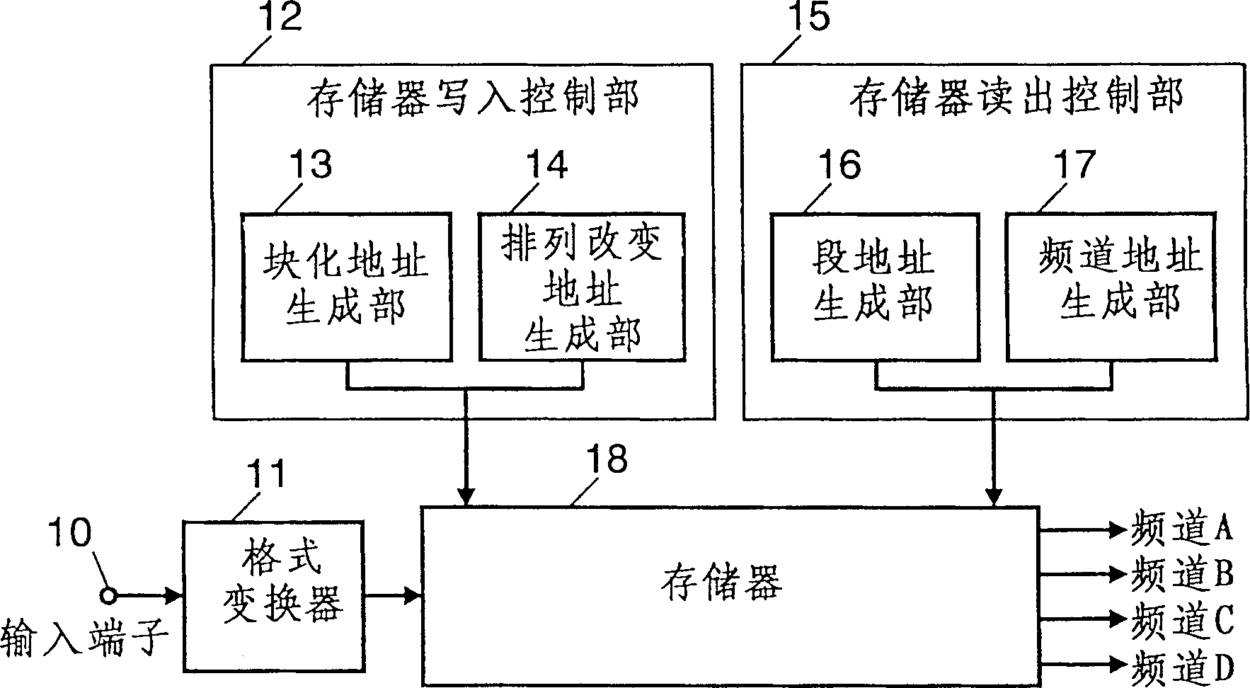
[0123] image 3 is a block diagram of an image signal shuffling device according to Embodiment 2 of the present invention.
[0124] exist image 3 in, for and figure 1 Blocks with the same actions are marked with the same symbols, and their descriptions are omitted.
[0125] exist image 3 In this case, the image signal input from the input terminal 10 is output to the format converter 11 .
[0126] The format converter 11 band-limits the input signal, and at the same time converts the number of pixels of the input signal.
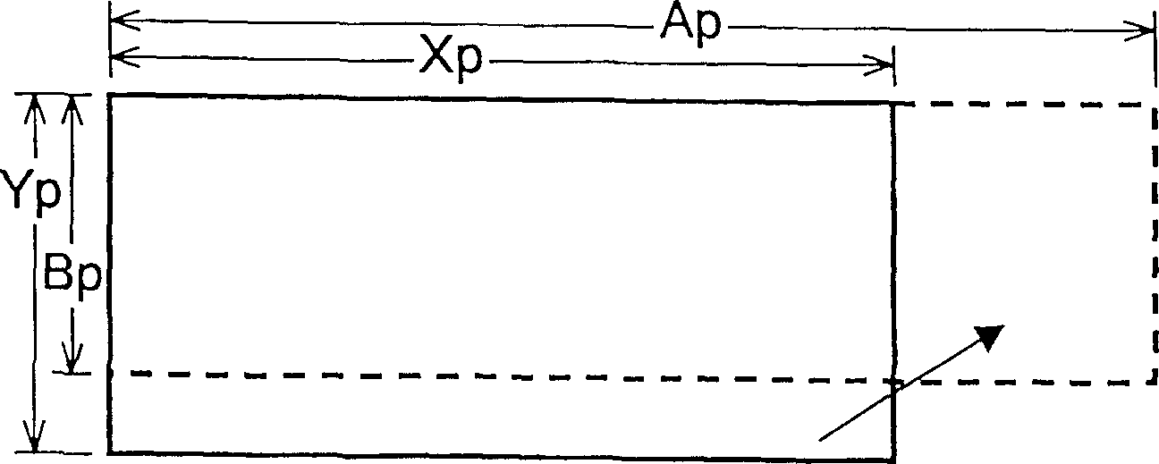
[0127] Here, it is assumed that the input signal is a signal whose number of horizontal pixels is Mp and the number of vertical lines is Np.
[0128] Here, it is assumed that Mp and Np are in the relationship of Mp≥Xp and Np≥Yp with respect to the signal of the number of horizontal pixels Xp and the number of vertical lines Yp of the input signal.
[0129] The format converter 11 performs band-limiting on the input pixels, and then thins out the pix...
Embodiment 3
[0133] Figure 4 It is a figure for explaining Example 3 of the present invention.
[0134] The block diagram of the image signal shuffling device of this embodiment and image 3 same.
[0135] Next, use image 3 and Figure 4 The operation of the image signal shuffling device of this embodiment will be described.
[0136] The number of effective lines is 1080, the number of effective pixels in the horizontal direction of the luminance signal (hereinafter, the table is Y signal) is 1920 pixels (the number of effective pixels per line) is 1920 pixels, and 2 color difference signals (hereinafter, tabled as Cr, Cb signal) the number of effective pixels in the horizontal direction is 960 pixels image signal (refer to Figure 4 (a)) Input to terminal 10.
[0137] The format converter 11 limits the frequency band to the input signal, converts the horizontal pixel number of the Y signal to 1280 pixels, and converts the horizontal pixel numbers of the Cr and Cb signals to 640 pi...
PUM
 Abstract
Description
Claims
Application Information