Method of detecting criticality of servo control system

A technology of servo control system and control parameters, which is applied in the field of servo parameter adjustment of the servo control system, and can solve problems such as damage to machinery, adjustment, and large oscillation sound

Inactive Publication Date: 2005-03-16
YASKAWA DENKI KK
View PDF0 Cites 0 Cited by
  • Summary
  • Abstract
  • Description
  • Claims
  • Application Information

AI Technical Summary

Problems solved by technology

However, in this method, the adjustment of the control parameters cannot be performed without starting the actual oscillation
Therefore, when using this method, the actual oscillation occurs before the adjustment of the control parameters, and due to the influence of this oscillation, there is a problem of damage to the machinery connected to the servo motor and a loud oscillation sound.

Method used


Image

  • Method of detecting criticality of servo control system
  • Method of detecting criticality of servo control system
  • Method of detecting criticality of servo control system

Examples


Embodiment Construction

[0030] best practice

[0031] Hereinafter, a method for detecting a critical oscillation of a servo control system according to an embodiment of the present invention will be described in detail with reference to the accompanying drawings. In all the drawings, constituent elements attached with the same symbols represent the same components.

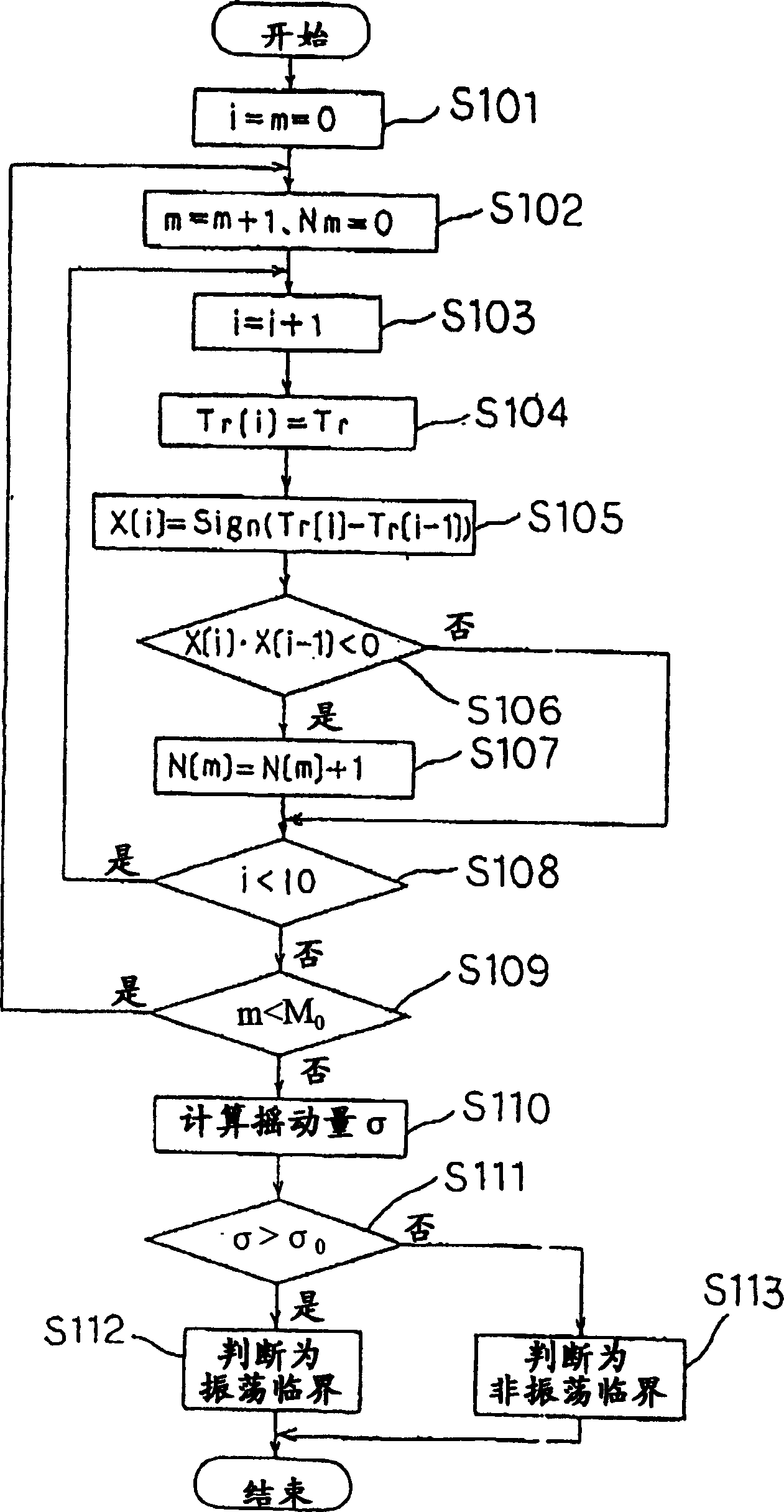
[0032] The oscillation critical detection method of the servo control system in this embodiment focuses on Figure 9 The relationship between control parameters such as proportional gain Kv, reciprocal Ki of integral time constant, differential time Kd, etc., torque command Tr, and vibration frequency component of speed feedback amount ω, that is, shaking amount, is shown. In the vibration critical detection method of the servo control system of this embodiment, the value of the control parameter is set to a value that increases step by step, and at the same time, the torque command Tr and the shaking amount of the speed feedback amount...


PUM


Abstract

Control parameters are regulated without oscillating a servo control system. Respective control parameters P[p] (p=0, 1 ---), arranged in the order of gradually increasing a chance of oscillating the servo control system, are set sequentially starting with P[0], a torque command Tr or a fluctuation amount sigma, showing a variation in frequency component of vibration of a speed feedback amount omega, is determined for each of control parameters, and the servo control system is assumed to have reached an oscillation criticality when a fluctuation amount sexceeds a specified value to thereby reset a control parameter set at that time to P[p-q] (q; natural number) or to P[0].

Description

technical field [0001] The invention relates to an oscillation critical detection method of the servo control system for detecting the oscillation critical state of the servo control system and adjusting control parameters. Background technique [0002] Usually, in order to control the control object in the servo control system, feedback control is performed, that is, the operation amount of the control object is obtained from the deviation between the command issued by the host device and the actual control amount. Figure 5 It is a block diagram showing the configuration of the servo control system for speed control. The servo control system is composed of a subtractor 1, a speed controller 2, a torque amplifier 3, a servo motor (M) 4, an encoder (E) 5, a machine 6, and a differentiator 7. The speed controller 2 is a control device for controlling the machine 6 to be controlled, that is, a proportional-integral-derivative controller (hereinafter referred to as a PID contro...

Claims


Application Information

Patent Timeline
Patent Type & Authority Patents(China)
IPC IPC(8): G05B5/01G05B13/02H02P29/00
CPCG05B13/024G05B5/01G05B21/02G05B2219/41112
Inventor 富田浩治
Owner YASKAWA DENKI KK
Why Eureka
Try Eureka