

Pressure suppression pipe and pressure suppression pool applying pressure suppression pipe
A technology for suppressing water pools and pressure pipes, applied in the field of nuclear power, can solve problems such as affecting the safety of nuclear facility systems, damage to surrounding related facilities, etc., and achieve the effects of suppressing water hammer, increasing safety and reliability, and simplifying working methods.
- Summary
- Abstract
- Description
- Claims
- Application Information
AI Technical Summary
Problems solved by technology
Method used
Image

Examples
Embodiment 1
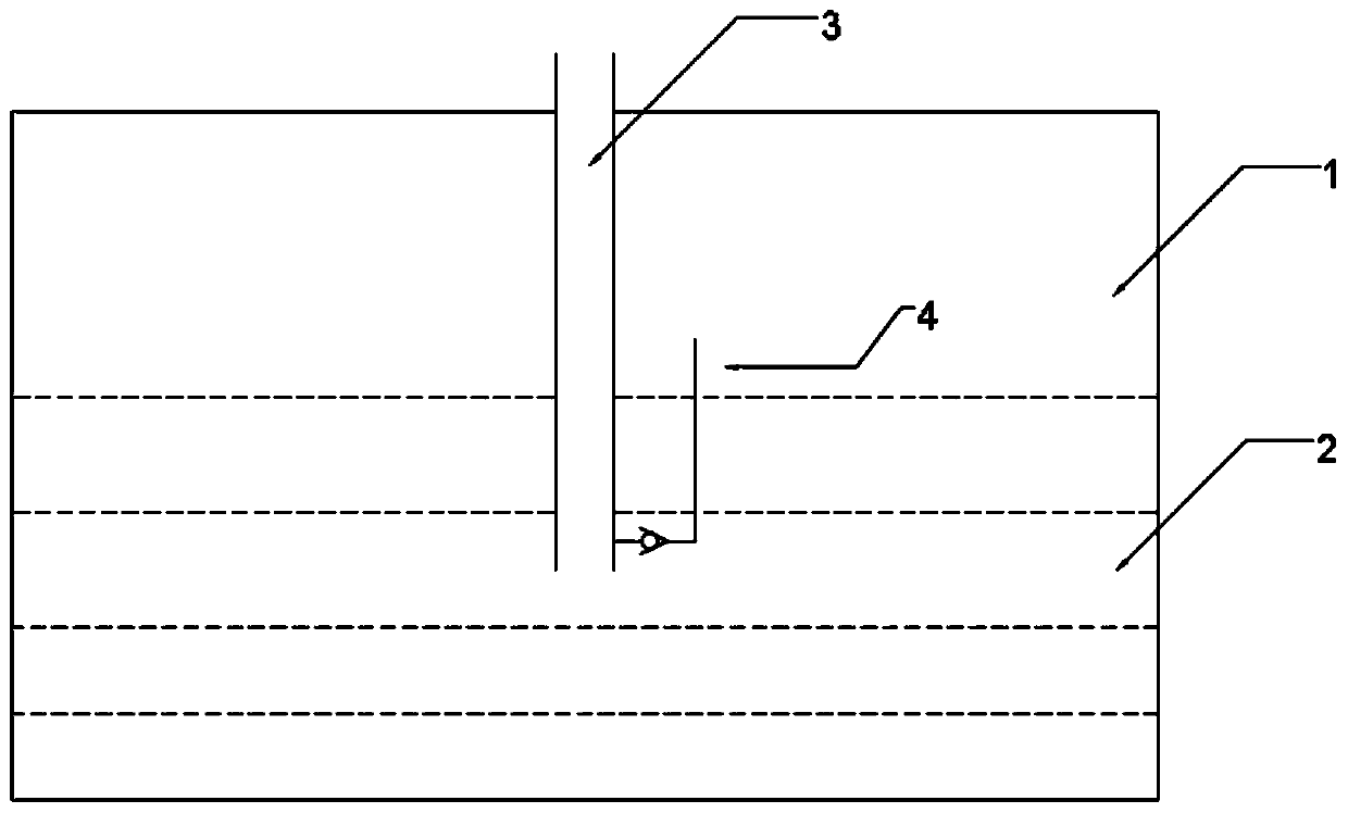
[0028] combine figure 1 , The decompression pool is installed in the safety shell, including the air space 1, the water space 2, and the decompression pipe 3. The air space 1 is initially filled with non-condensable gas of 1 atmosphere pressure, mainly air, the water space 2 contains supercooled water for condensation, and one end of the suppression pipe 3 is immersed in the supercooled water contained in the water space 2 of the suppression pool , the suppression pipe 3 connects the water space 2 of the suppression pool and the air space in the containment, and the suppression pipe 3 has a suppression pipe inlet connected with the gas space of the containment and a suppression pipe connected with the water space of the containment pool Tube outlet. The ventilated suppression pipe 3 penetrates the pool deep below the liquid surface and is fixedly connected with the suppression pool. Its function is to transfer the mixture of steam and air in the containment from the gas space...
Embodiment 2
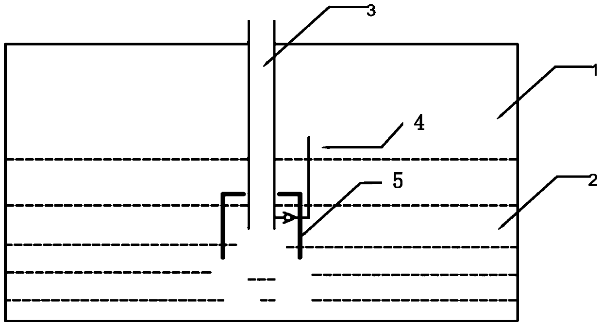
[0032] combine figure 2, on the basis of Example 1, an enclosure 5 for suppressing pressure oscillations is added in the water space 2, the enclosure 5 is cylindrical and barrel-shaped around, and its top is located below the water surface of the water space 2 and above the outlet of the pressure suppression pipe, The bottom is located under the outlet of the suppression tube submerged in the liquid. The bottom has a certain distance from the bottom of the water space 2. It has a ring structure around the suppression tube 3 and is concentric with the suppression tube 3. The enclosure 5 is connected to the suppression pool or The pressure suppression pipe is fixedly connected, and the design purpose of the enclosure 5 is to weaken the condensation driving potential of the steam jet condensation process by increasing the water temperature around the pressure suppression pipe 3, thereby suppressing the pressure oscillation generated during the jet condensation process. In partic...
Embodiment 3
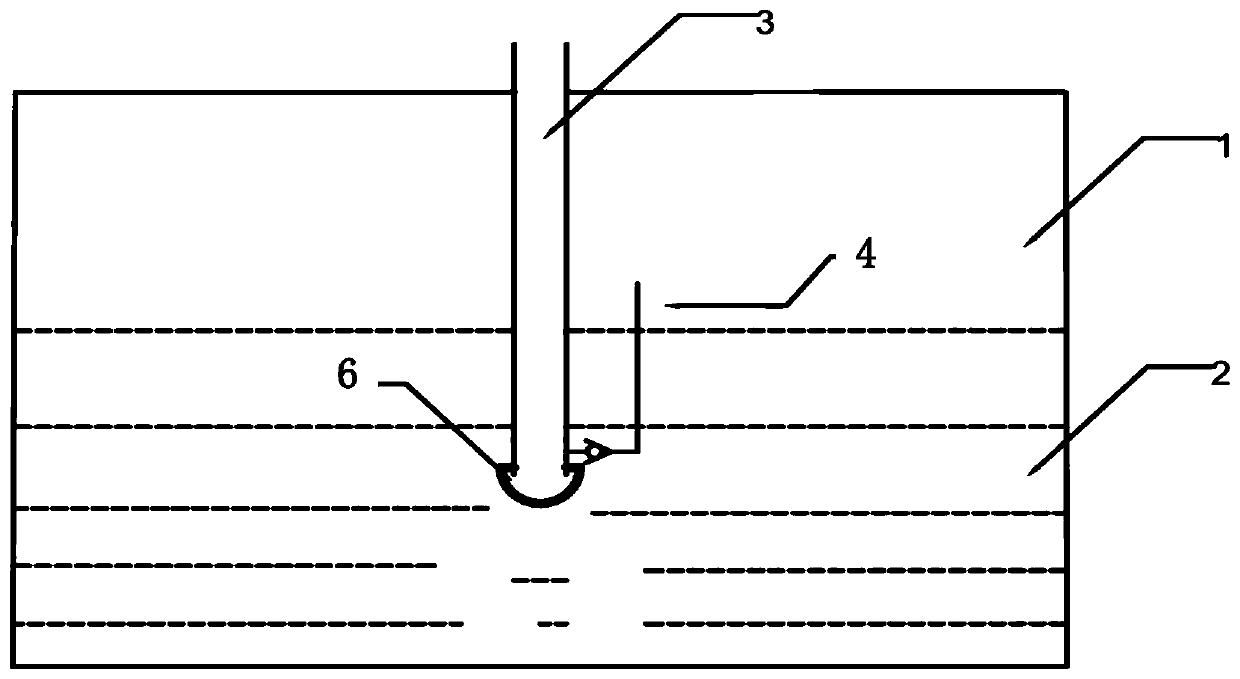
[0035] combine image 3 , on the basis of Embodiment 1, the outlet of the pressure suppression tube 3 submerged in the liquid is additionally provided with a bubble cutting component 6 . The bubble cutting part 6 is located at the outlet of the pressure suppression pipe 3, and its purpose is to cut the large bubbles generated at the outlet of the pressure suppression pipe 3 into small bubbles, and weaken the pressure oscillation by breaking the bubbles. When high-temperature steam is injected into the decompression pool, bubbles will be generated at the outlet, and the bubbles will condense with water and eventually collapse and disappear. The water hammer induced by the bubble collapse is the cause of pressure oscillation. At this time, the bubble cutting part 6 set at the outlet of the pressure suppression tube can cut the large bubbles generated at the outlet into small bubbles, thereby reducing the intensity of the pressure oscillation.
[0036] The bubble cutting part us...
PUM
 Abstract
Description
Claims
Application Information