
Rotor position detecting method of brushless DC motor having no sensor

A technology of rotor position detection and brushed DC motor, which is applied in the direction of electronic commutator, electronic commutation motor control, electrical components, etc., can solve the problems of motor out of slot and difficult to return to normal state, and achieve the effect of stable driving

Inactive Publication Date: 2005-04-20
LG ELECTRONICS (TIANJIN) APPLIANCES CO LTD
View PDF0 Cites 1 Cited by
  • Summary
  • Abstract
  • Description
  • Claims
  • Application Information

AI Technical Summary

Problems solved by technology

In the above cases, if the error of the position signal becomes large, it will be difficult to restore the motor to the normal state.

Method used


Image

  • Rotor position detecting method of brushless DC motor having no sensor
  • Rotor position detecting method of brushless DC motor having no sensor
  • Rotor position detecting method of brushless DC motor having no sensor

Examples


Embodiment Construction

[0037] Embodiments of the present invention will be described in detail below with reference to the accompanying drawings.

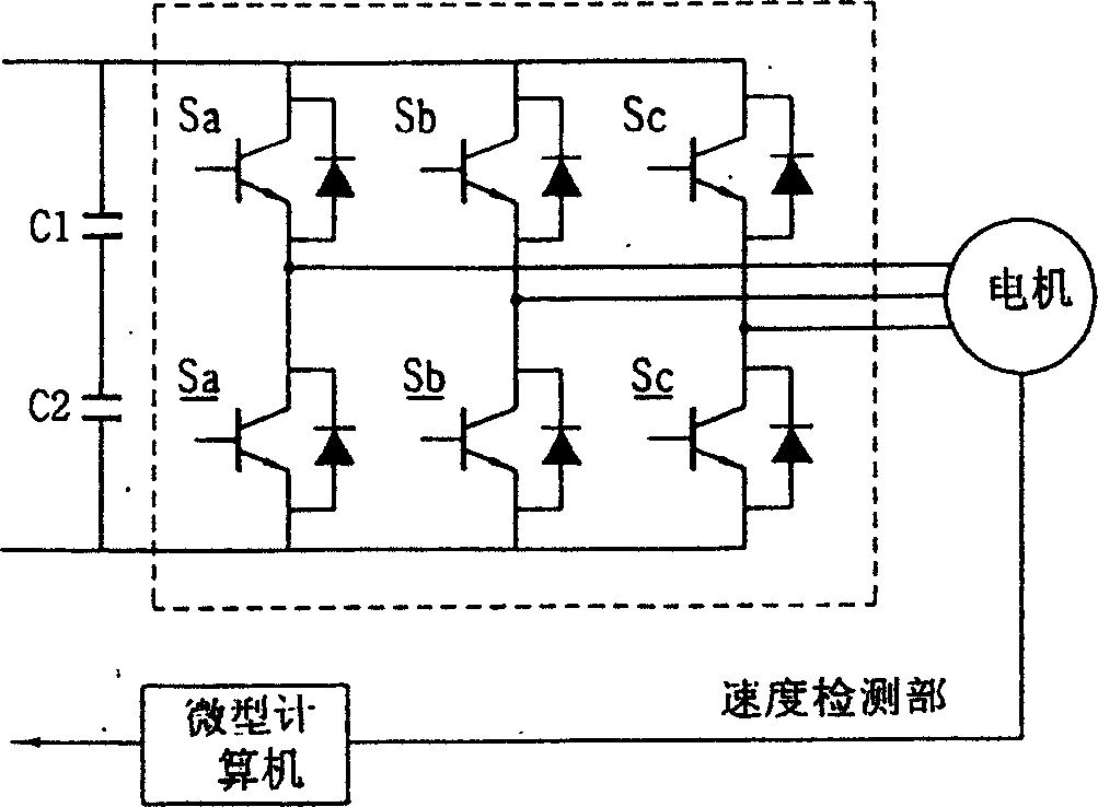
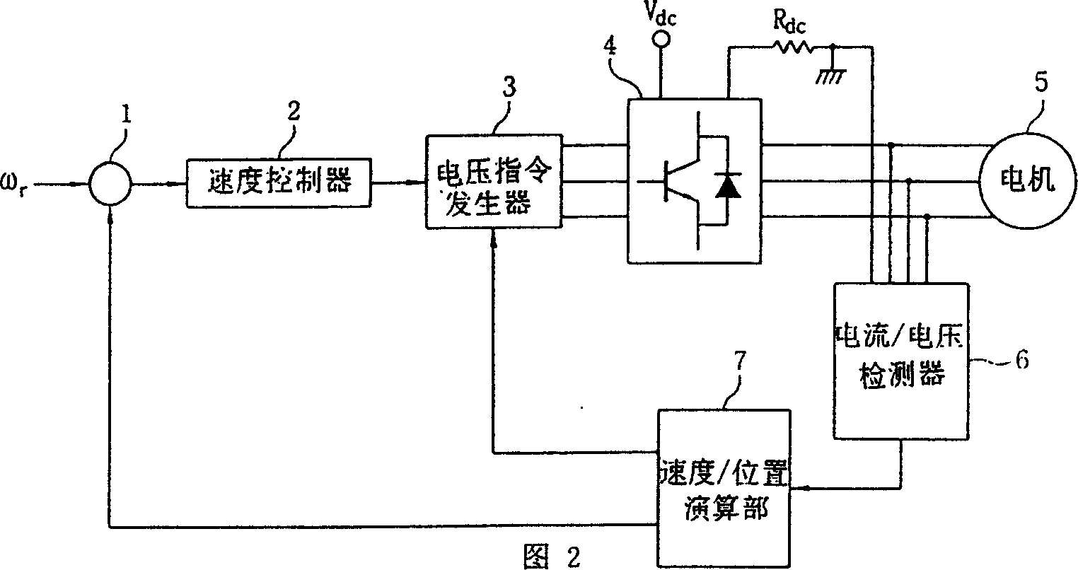
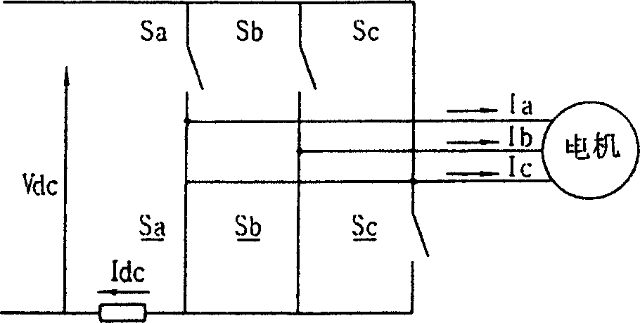
[0038] The invention is a sensorless rotor position detection method for a brushless DC motor. The method and the device used are the same as those of the prior art shown in FIG. 2 . Fig. 4 is a working flow diagram of the present invention. As shown in Figure 4, the sensorless rotor position detection method of the brushless DC motor of the present invention includes the following steps: the first step: judging whether the user has selected the position information correction mode; the second step: if it is not the position information correction mode, then Use the current and voltage of 'A, B, C' phases to estimate the position of the main rotor and drive the motor; the third step: if it is the position information correction mode, cut off the phase currents of 'A, B, C' phases , to detect the phase voltages of the 'A, B, C' phases; the fourth step: ...


PUM


Abstract

A method without sensor for detecting the position of rotor for brush-less DC motor includes such steps as judging if a position information correction mode is chosen, if not, deriving the rotor position from the currents and voltages of phases A, B and C, and if it is, cutting off the currents of phases A, B and C, detecting their phase voltages, and calculating their counter-EMFs to detect the position information of rotor.

Description

technical field [0001] The invention relates to a method for detecting the rotor position of a direct current motor, in particular to a sensorless rotor position detection method for a brushless direct current motor. Background technique [0002] The relevant prior art will be described in detail below with reference to the accompanying drawings. [0003] figure 1 There is already a drive circuit for a brushless motor. As shown in the figure, the driving circuit of the brushless motor is: capacitors C1 and C2 are connected in series, and the series capacitor is to stabilize the rectified AC power supply; the frequency converter converts the DC voltage of the capacitors C1 and C2 according to the control signal of the microcomputer into a three-phase AC voltage; the motor is driven by the three-phase AC voltage of the frequency converter; the microcomputer uses the voltage and current applied to the motor to detect the position of the motor rotor, and then the microcomputer...

Claims


Application Information

Patent Timeline
Patent Type & Authority Patents(China)
IPC IPC(8): H02P6/182
Inventor 梁淳培赵宽烈洪讃熙
Owner LG ELECTRONICS (TIANJIN) APPLIANCES CO LTD
Learn More