
Metal bat with pressurized bladder in hitting zone

A technology of metal balls and bats, applied in the direction of rackets, sports accessories, etc.

Inactive Publication Date: 2005-05-11
HILLERICH & BRADSBY
View PDF2 Cites 0 Cited by
  • Summary
  • Abstract
  • Description
  • Claims
  • Application Information

AI Technical Summary

Problems solved by technology

However, the prior art does not address the use of one or more pressurized bladders within the strike zone of a hollow metal bat that are precisely positioned and maintained within the strike zone

Method used


Image

  • Metal bat with pressurized bladder in hitting zone
  • Metal bat with pressurized bladder in hitting zone
  • Metal bat with pressurized bladder in hitting zone

Examples


Embodiment Construction

[0041] In describing the preferred embodiment of the invention illustrated in the drawings, specific terminology will be employed for the sake of clarity. It is not intended, however, to limit the invention to the specific embodiments and terminology chosen; it should be understood that each specific term includes all technically equivalent terms which could be used in a similar manner to achieve similar purpose.

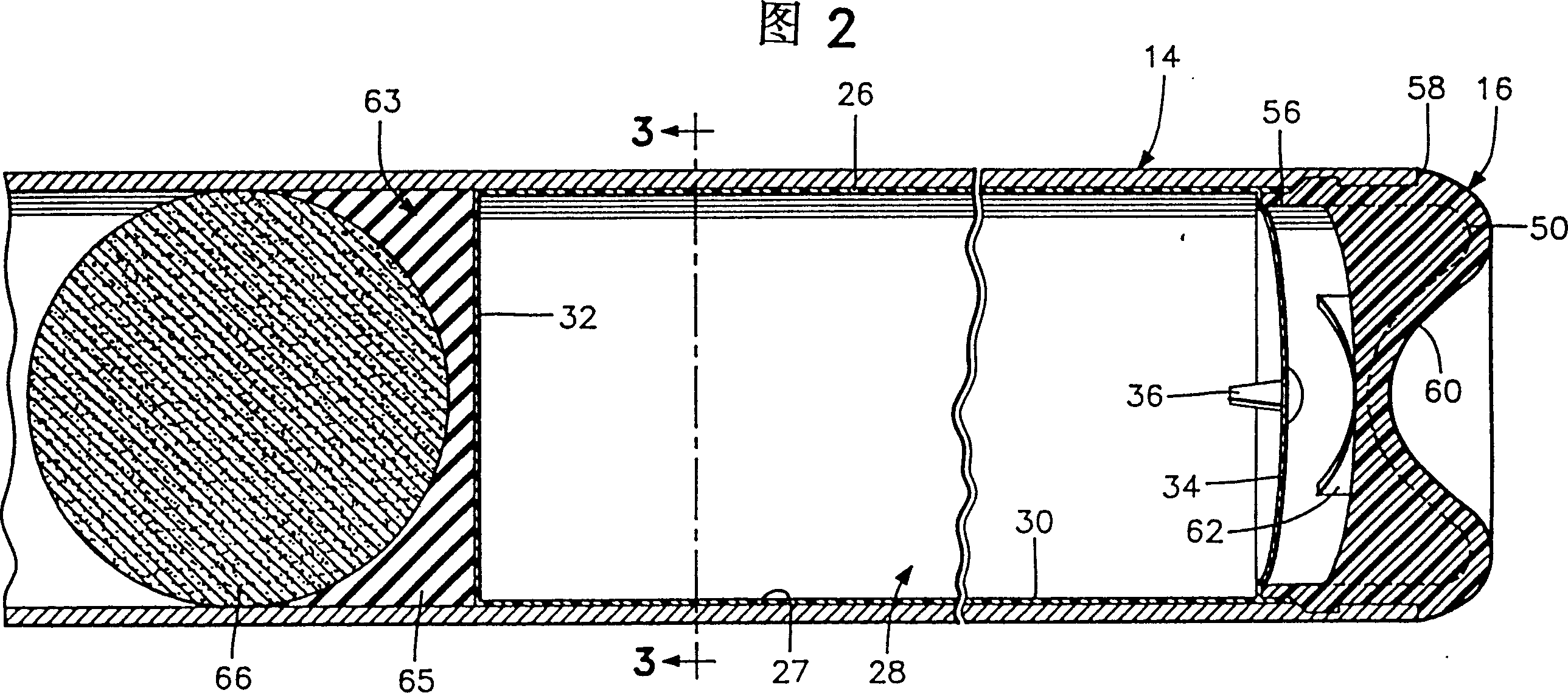
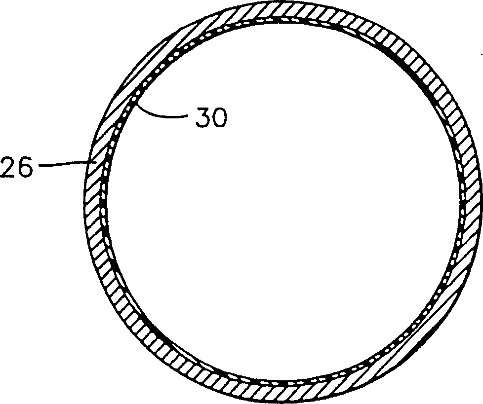
[0042] Referring to the embodiment illustrated in Figures 1 to 4, the hollow metal bat is generally indicated by the reference numeral 10 and includes a hollow shaft 12 extending the length of the bat. Included at the distal end of the shaft 12 is a hitting zone generally indicated by reference numeral 14 which is provided with an end cap 16 to form a distal closure. Shaft 12 also includes a tapered transition region 18 extending from the proximal end of striking zone 14 to the handle generally indicated by reference numeral 20 . The handle 20 includes a cap 22 at...


PUM


Abstract

A metal bat consists of a tubular shaft with a hitting zone and end cap at the far end of the bat, a grip at the proximal end of the bat, and a pressurized bladder located within the shaft and hitting zone. A method of inserting and positioning a pressurized bladder at the strike zone is also disclosed. Various types of pressurized bladders are disclosed, including various valves in the barrel to pressurize the bladders. The bladder may comprise one or several individual bladders or compartments designed to occupy predetermined strike zone length locations.

Description

technical field [0001] The present invention relates to a tubular metal bat, such as a baseball or softball bat, comprising a tubular shaft having a striking zone and end cap at a distal end, a grip at a proximal end, and an insert within the striking zone. A pressurized bladder in a tubular rod body. The invention also relates to a method of inserting and securing a pressurized bladder in the strike zone. Background technique [0002] Hollow metal bats made of aluminum or similar materials have been developed and used for many years in baseball, softball, etc. Since their inception, many improvements and studies have been made to the construction of hollow metal bats. These improvements and studies are described in earlier US Patent Nos. 5,393,055, 5,421,572 and 5,494,280. In addition, various closure caps and closure structures are conventionally employed to enhance the distal end of such bats. Attempts have been made to pad and reinforce the bat by filling the interio...

Claims


Application Information

Patent Timeline
IPC IPC(8): A63B59/06
CPCA63B60/24A63B60/10A63B60/06A63B60/08A63B2102/18A63B59/56A63B2102/182A63B59/51A63B59/58A63B2059/581A63B59/50
Inventor 小杰克·W·麦凯卡特·K·麦凯杰克·W·麦凯三世
Owner HILLERICH & BRADSBY
Learn More