
Automatic speed changer for car

A technology of automatic transmission and main transmission, applied in the direction of vehicle gearbox, transmission element, transmission device, etc., can solve the problems of high production cost, complicated control, and increase of control factors, and achieves reduction of vibration, simplification of control system, and reduction of factors. Effect

Inactive Publication Date: 2005-10-26
HONDA MOTOR CO LTD
View PDF1 Cites 2 Cited by
  • Summary
  • Abstract
  • Description
  • Claims
  • Application Information

AI Technical Summary

Problems solved by technology

As a result, more factors need to be controlled when changing gears, and the control becomes extremely complicated, resulting in high production costs

Method used


Image

  • Automatic speed changer for car
  • Automatic speed changer for car
  • Automatic speed changer for car

Examples


Embodiment Construction

[0023] Referring to Figs. 1 to 4, a first embodiment according to the present invention will be described below.

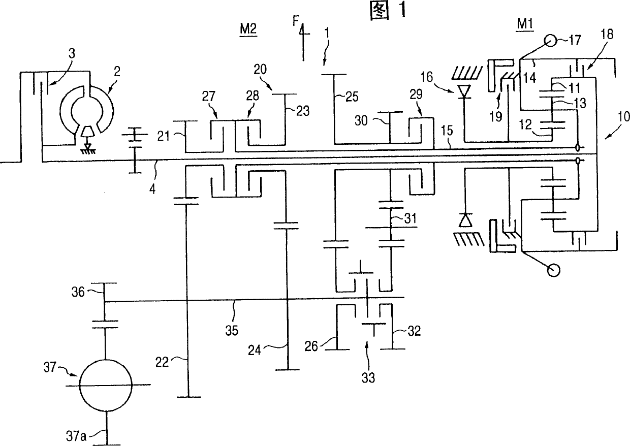
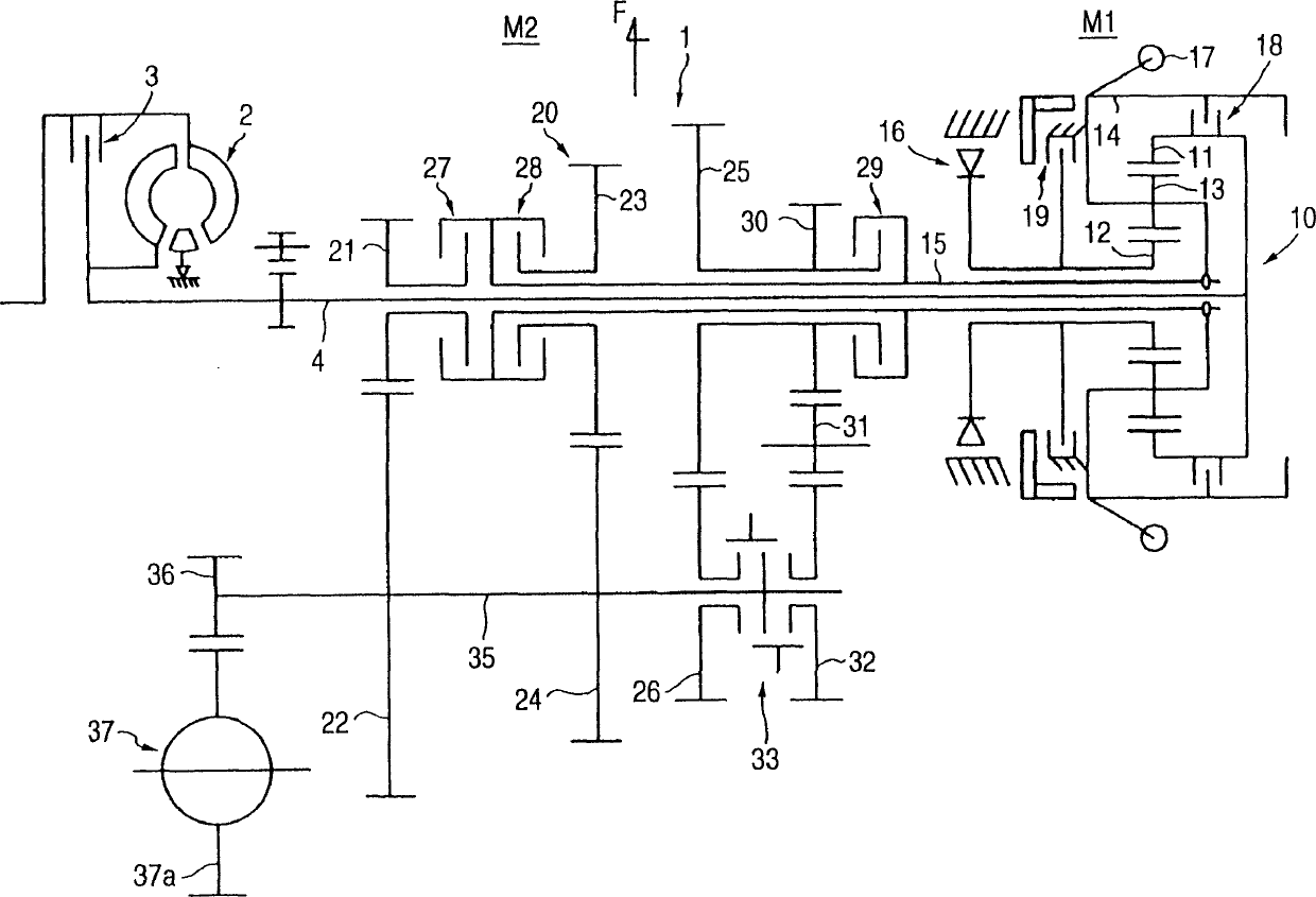
[0024] Fig. 1 shows a schematic structural diagram of an automatic transmission 1 designed as a front-engine front-wheel drive (FF type vehicle) according to an embodiment of the present invention.

[0025] An internal combustion engine (not shown) is arranged transversely on the left-hand side of the front of the vehicle body, and its output is transferred to an input shaft 4 extending to the right side through a torque converter 2 and a lockup clutch 3 .

[0026] The input shaft 4 including a main shaft extends to the right by a certain length, and a planetary gear set 10 is provided at the right end of the thus extended input shaft 4 .

[0027] The planetary gear set 10 includes a ring gear 11, a sun gear 12 and planetary gears 13, all of which are helical gears. The ring gear 11 is integrally connected with the input shaft 4, and at the same time, includes a ...


PUM


Abstract

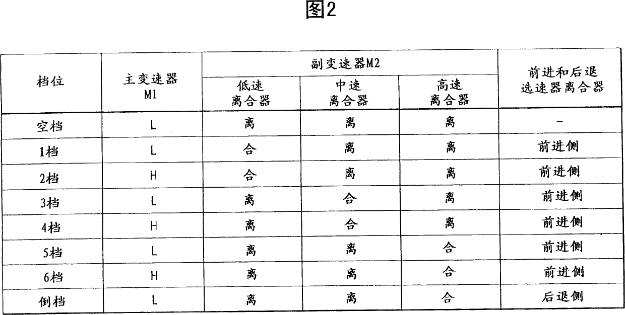
An automatic transmission has: a primary transmission mechanism including: an input shaft; a planetary gear set having a sun gear, planetary gears and a ring gear, each being a helical gear, the ring gear and sun gear being respectively connected to the input shaft and to a stationary member via a one-way clutch, and a carrier for the planetary gears is connected to a primary output shaft; and an centrifugal clutch engaged / released the input shaft with / from the primary output shaft in correspondence with a centrifugal force by a weight and a thrust force by the helical gear; and a secondary transmission mechanism connected to the primary output shaft, for controlling a gear-shift into two or more speed-changed conditions. A multiplicity of change-speed gears is obtained by selectively combining the released and engaged states of the centrifugal clutch for each of the speed-changed conditions of the secondary transmission mechanism.

Description

Technical field: [0001] The invention relates to a vehicle automatic transmission, which is composed of two transmissions connected together. Background technique: [0002] An example of such an automatic transmission is described in JP-B-5-67831. [0003] This example is an automatic transmission, in which a main transmission and an auxiliary transmission are connected in series, the main transmission realizes the conversion of multiple shifting states, and the auxiliary transmission realizes the conversion between high-speed state and low-speed state. Thus, a variety of shifting gears are formed through the combination of the respective shifting states in the main and auxiliary transmissions. [0004] During a gear change, there is a situation where both transmissions change gears in opposite directions to each other. [0005] For example, if the entire transmission is to be shifted up to the high-speed side through a gear, a situation arises where the main transmission ...

Claims


Application Information

Patent Timeline
Patent Type & Authority Patents(China)
IPC IPC(8): B60K17/26F16H3/089F16H3/54F16H37/04F16H47/06F16H61/08F16H63/24
CPCF16H61/0437F16H2200/0052F16H61/0295F16H37/046F16H61/70
Inventor 熊谷赖範高桥司楢木哲生
Owner HONDA MOTOR CO LTD
Learn More