
Device for fitting outdoor unit of split air-conditioner

An outdoor unit, split-type technology, applied in air conditioning systems, heating methods, supporting machines, etc., can solve problems such as the impact of outdoor unit 41, and achieve the effect of safe installation

Inactive Publication Date: 2005-11-23
PANASONIC CORP
View PDF0 Cites 0 Cited by
  • Summary
  • Abstract
  • Description
  • Claims
  • Application Information

AI Technical Summary

Problems solved by technology

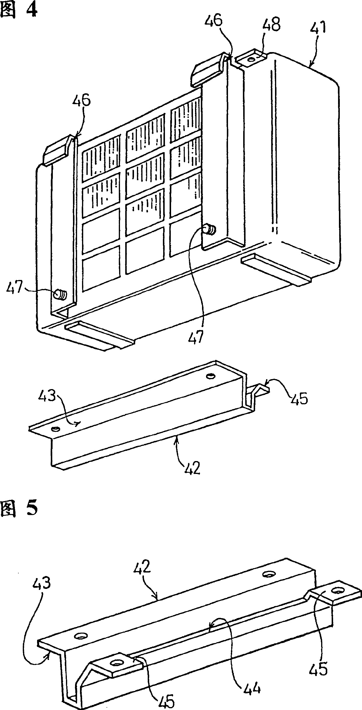
However, in this method, there will be a problem that the lower part of the outdoor unit 41 is subjected to vibration shocks such as being blown by a typhoon or an earthquake.

Method used


Image

  • Device for fitting outdoor unit of split air-conditioner
  • Device for fitting outdoor unit of split air-conditioner
  • Device for fitting outdoor unit of split air-conditioner

Examples


Embodiment Construction

[0020] Embodiments of the present invention will be described below with reference to the accompanying drawings.

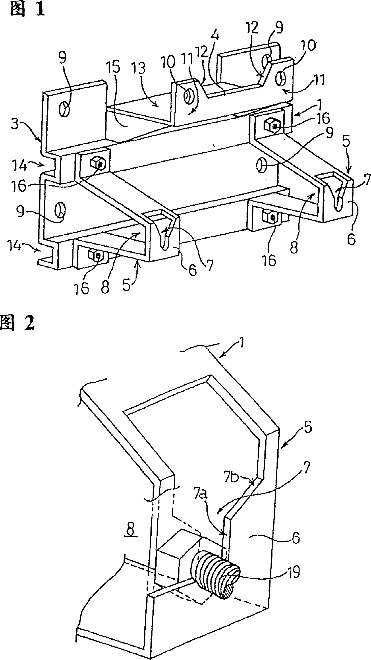
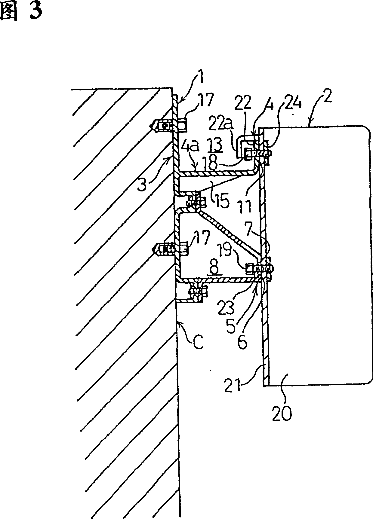
[0021] An embodiment of the outdoor unit of the split type air conditioner of the present invention is shown in Fig. 1 and Fig. 2, with: a direct installation part 3 made of sheet metal that is against the wall surface and directly fixed with bolts, and the direction of the direct installation part 3 is A left and right extending holding part 4 protruding forward and bent upward, and a pair of left and right posture maintaining parts 5 whose bases are fixed by bolts 16 on the direct mounting part 3 below the holding part 4 .

[0022] An example of the outdoor unit 2 is represented by Fig. 3, with an integrally arranged on the back 21 top of its casing 20, and the first matching portion 22 with its front end 22a that is open downwards forms a first L-shaped part, which includes the front end The 1st matching part 22 of 22a constitutes a first L-shaped part, and the...


PUM


Abstract

An unit installation tool for a separate type air conditioner is capable of installing the output unit easily and safely on the outer wall, and preventing shaking or swaying. A yoke is fitted to the outer wall with bolts. A holding part extended laterally is provided in the upper part of this yoke. The holding part has a first engaging part provided in the upper part of the rear surface of the unit engaged from above, for stopping it from beneath, and a position keeping part provided below the first engaging part of the yoke, having a second engaging part provided beneath the first engaging part of the unit engaged from above, for defining the longitudinal movement of the lower side of the unit.

Description

technical field [0001] The present invention relates to an optimum outdoor unit mounting device for a split-type air conditioner for installing the outdoor unit of the split-type air conditioner on an outer wall surface such as under a window. Background technique [0002] As shown in Figure 7, the outdoor unit 51 of the split type air conditioner usually accommodates the heavy compressor 53 in order to effectively reduce the composition of the indoor unit not shown in the figure, and to make it light and small. In the box 52. For this reason, the outdoor unit 51 is heavier than the indoor unit, and thus generally utilizes the established mounting feet 54 at the bottom to be installed on the established platform above the ground, balcony or the foot of the house. The mounting feet 54 securely fasten the mounting holes 54a mounted on the setting table with bolts. However, depending on different occasions, the place where the installation table is installed is constantly cha...

Claims


Application Information

Patent Timeline
IPC IPC(8): F16M13/02F24F1/62F24F5/00F24F13/32
CPCF24F13/32F24F1/62
Inventor 波多野弘司中沼三雄
Owner PANASONIC CORP
Learn More