Electric rotary shaver

A technology of electric rotation and razor, which is applied in metal processing and other directions, and can solve the problems of limited inclination angle and difficulty in increasing the inclination angle of the outer blade 22

Inactive Publication Date: 2006-02-01
IZUMI PROD CO
View PDF0 Cites 3 Cited by
  • Summary
  • Abstract
  • Description
  • Claims
  • Application Information

AI Technical Summary

Problems solved by technology

Therefore, the inclination angle of the outer blade 22 is limited
As can be seen from the above, in the existing electric shaver, because the inclination angle of the outer blade 22 is limited by the positional relationship between the outer blade 22 and the outer blade hole 44, it is difficult to increase the inclination angle of the outer blade 22.

Method used


Image

  • Electric rotary shaver
  • Electric rotary shaver
  • Electric rotary shaver

Examples


Embodiment Construction

[0032] Preferred embodiments of the electric rotary shaver of the present invention will be described in detail below with reference to the accompanying drawings.

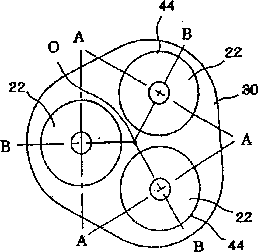
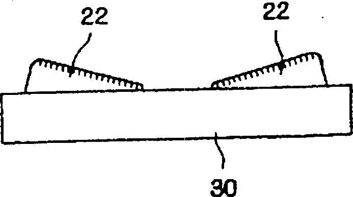
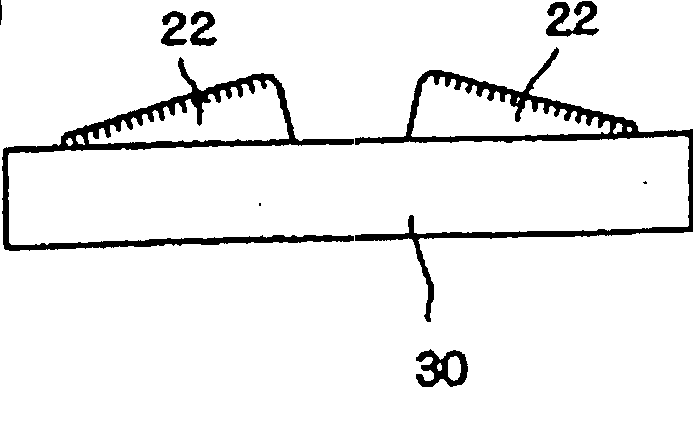
[0033] The electric rotary shaver of the present invention is characterized in that each outer blade 22 is supported by a pair of pivots arranged perpendicularly to each other, so that the outer blade 22 can be tilted in the outer blade hole 44 of the knife holder 30 .

[0034] figure 1 is a schematic diagram showing a supporting manner in which the outer blade 22 is pivotally supported in the blade holder 30 . Three outer blades 22 are positioned within the tool holder 30 such that the center of the outer blades 22 is located at the vertices of an equilateral triangle.

[0035]Positions A and B are where the pivots are arranged. The pivot axis for tiltably supporting each outer blade 22 is located on two imaginary lines passing through the center of each outer blade 22 and perpendicular to each other. In this ...


PUM


Abstract

An electric rotary shaver comprising: a cutter frame having a plurality of outer cutter holes, outer cutters disposed in outer cutter holes so as to be tiltable in any direction, and inner cutters rotatably disposed inside the outer cutters and connected to inner cutter drive shafts that are rotationally driven and urged in a direction that causes the inner cutter drive shafts to protrude outward; wherein a cutter retaining plate is provided inside the cutter frame so as to be on a main body side of the electric shaver, and fulcrum plates are tiltably shaft-supported in the cutter retaining plate so as to be positionally correspond to the outer cutter holes; and the outer cutters are shaft-supported in the fulcrum plates via supporting members in a direction that is perpendicular to the direction in which the fulcrum plates are shaft-supported by the cutter retaining plate, thus being tiltable.

Description

technical field [0001] The present invention relates to an electric rotary shaver, in particular to a structure capable of tiltably supporting an outer blade in a knife holder of the electric rotary shaver. Background technique [0002] Figure 9 It is a three-dimensional view of the overall structure of the existing electric rotary shaver. In this type of electric shaver 10 , the cutter head 20 is detachably installed on the upper part of the main body casing 12 . Three outer blades 22 are mounted in the cutter head 20 such that the centers of the outer blades are located at the vertices of an equilateral triangle. Slits for introducing hair are formed on the outer blade 22 in the radial direction. On each outer blade 22, an annular outer hair introduction region V and an inner hair introduction region W are formed concentrically, and a groove is formed on a boundary area between the outer hair introduction region V and the inner hair introduction region W. [0003] Fi...

Claims


Application Information

Patent Timeline
Patent Type & Authority Patents(China)
IPC IPC(8): B26B19/14
CPCB26B19/141B26B19/145
Inventor 内山圣参中野毅川船乡一泉幸雄
Owner IZUMI PROD CO
Why Eureka
Try Eureka