Headrest supporting structure

a technology for supporting structures and headrests, which is applied to head rests, vehicle components, vehicle arrangements, etc., can solve problems such as reducing drivability, and achieve the effects of reducing the width of the tilt range, preventing the width of the pivot range from being easily changed, and increasing the tilt range of the headrest stay

Inactive Publication Date: 2018-02-06
TOYOTA JIDOSHA KK
View PDF12 Cites 1 Cited by
  • Summary
  • Abstract
  • Description
  • Claims
  • Application Information

AI Technical Summary

Benefits of technology

[0007]Accordingly, it is an objective of the present invention to provide a headrest supporting structure that reduces variation in the attenuation property of vibration generated in a seat by reducing variation in a pivot range of a headrest with respect to a backrest in the front-rear direction.Means for Solving the Problems
[0010]In the above-described headrest supporting structure, the first spring, which has a stiffness higher than that of the second spring, is located more distant from the stopper section in the seat vertical direction than the second spring. Thus, as compared to a case in which the stiffnesses of the springs are the same, the above-described center of tilting is set to a position distant from the stopper section. In this case, if the width of the pivot range of the headrest is the same, the tilt range of the headrest stay is increased by an amount corresponding to the increase in the range in which the displacement of the stopper section in the front-rear direction is permitted as compared to the case in which the stiffnesses of the springs are the same. Thus, even if the width of the tilt range is changed due to errors in the sizes and the shapes of the headrest stay and various components that configure the headrest supporting structure and assembly errors in various components, the ratio of the change amount in the width of the pivot range of the headrest to the change amount in the width of the tilt range is reduced. That is, the width of the pivot range is kept from being easily changed. Thus, variation in the width of the pivot range of the headrest is reduced, and variation in the attenuation property of vibration generated in the seat is reduced.
[0012]The stopper section may be located at a position more distant from the headrest in the seat vertical direction than the springs. In this case, the first spring, which has a high stiffness, is arranged in the vicinity of the headrest in the seat vertical direction, and the second spring, which has a stiffness lower than that of the first spring, is arranged distant from the headrest in the seat vertical direction. Thus, the headrest stay tilts about the center of tilting set closer to the headrest than the center between the springs. With this configuration, even if the initial position of the distal end of the headrest stay is displaced forward or rearward, the width of the pivot range of the headrest in the front-rear direction is less easily changed than in which the stiffnesses of the springs are the same. Thus, variation in the attenuation property of vibration generated in the seat can be reduced. The term “the initial position of the distal end of the headrest stay” refers to the position of the distal end of the headrest stay in the front-rear direction when the headrest does not receive any force.
[0014]According to the above configuration, the center of tilting is set at a position distant from the stopper section by a relatively great distance in the seat vertical direction. In this case, if the width of the pivot range of the headrest is the same, the tilt range of the headrest stay is increased by an amount corresponding to the increase in the range in which the displacement of the stopper section in the front-rear direction is permitted as compared to a case in which the stiffnesses of the springs are the same. Thus, even if the width of the tilt range is changed due to errors in the sizes and the shapes of the headrest stay and various components that configure the headrest supporting structure and assembly errors in various components, the ratio of the change amount in the width of the pivot range of the headrest to the change amount in the width of the tilt range is reduced. That is, the width of the pivot range is kept from being easily changed. Thus, variation in the width of the pivot range of the headrest is reduced, and variation in the attenuation property of vibration generated in the seat is reduced.

Problems solved by technology

As a result, the frequency band of engine vibration during idling includes the resonance frequency of the vehicle seat, which reduces the drivability.

Method used


Image

  • Headrest supporting structure
  • Headrest supporting structure
  • Headrest supporting structure

Examples


first embodiment

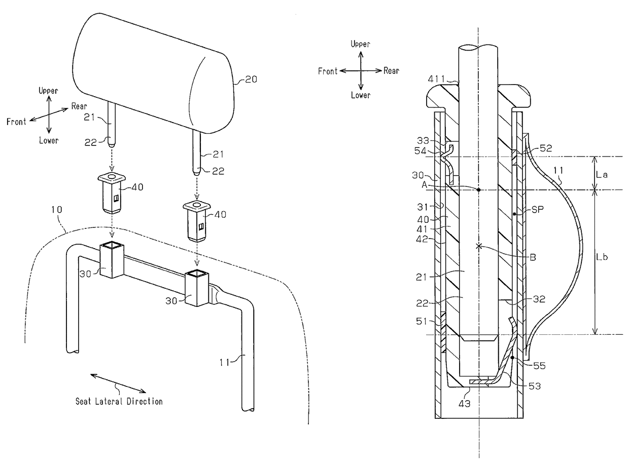
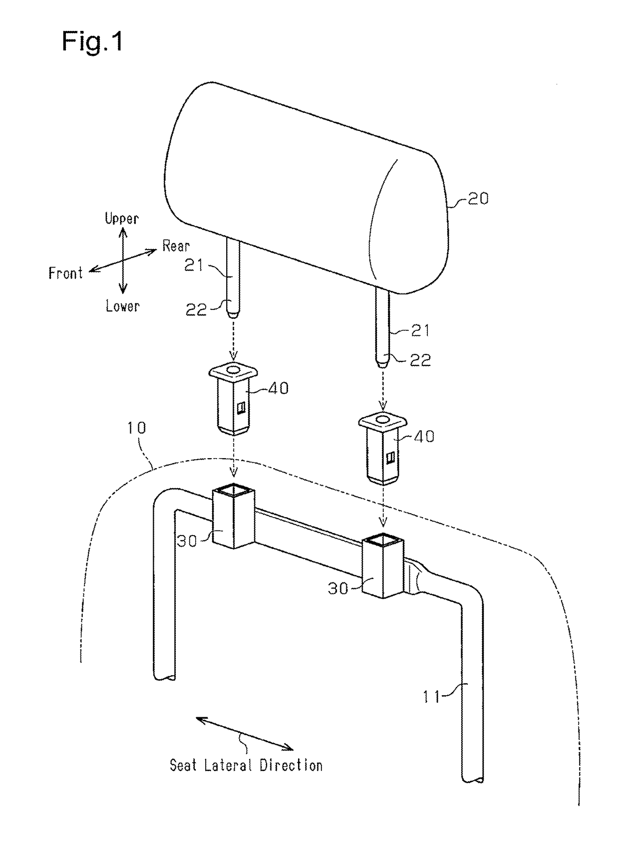
[0027]A headrest supporting structure according to a first embodiment applied to a seat installed in a vehicle will now be described with reference to FIGS. 1 to 6. In the present embodiment, the side of the headrest on which the head portion of a person seated in the seat is located is referred to as a front side, and the opposite side is referred to as a rear side. Furthermore, the direction in which the backrest and the headrest are arranged is referred to as a seat vertical direction.

[0028]FIG. 1 shows a headrest supporting structure, which elastically supports a headrest 20 on a backrest 10 of the seat. As shown in FIG. 1, the headrest 20 includes a pair of rod-like headrest stays 21. The headrest stays 21 are arranged in the lateral direction of the seat, and each headrest stay 21 has a distal end portion 22, which projects from the headrest 20 toward the backrest 10.

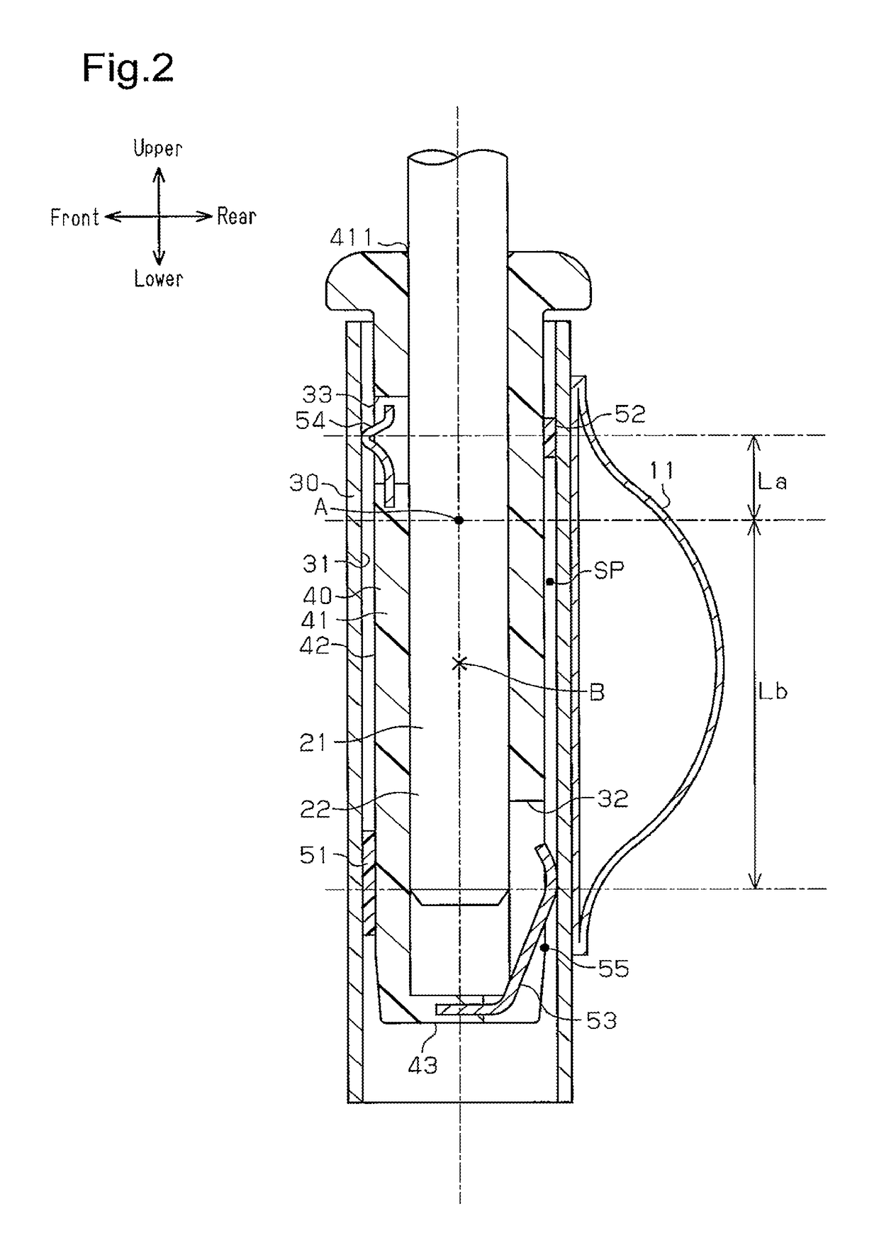
[0029]The headrest supporting structure includes a pair of support brackets 30, which is formed of metal into a...

second embodiment

[0055]A headrest supporting structure according to a second embodiment will now be described with reference to FIG. 7. In the following description, differences from the headrest supporting structure of the first embodiment will mainly be discussed. Like or the same reference numerals are given to those components that are like or the same as the corresponding components of the headrest supporting structure of the first embodiment, and detailed explanations are omitted.

[0056]As shown in FIG. 7, first communication windows 32A, which connect the inside and the outside of the headrest support 40, are provided on the lower rear side and the lower front side of the headrest support 40. A lower spring 53A, which is supported by the bottom wall 43 of the substantially tubular headrest support 40, has a first urging portion 531, which extends obliquely upward and rearward from the bottom wall 43, and a second urging portion 532, which extends obliquely upward and forward from the bottom wa...


PUM


Abstract

A headrest supporting structure is provided with a lower spring and an upper spring, which are located at different positions in the vertical direction of a seat. The structure elastically supports a headrest stay with the springs. When a stopper section, which changes the position in the front-back direction in accordance with pivoting of the headrest, comes into contact with a support bracket, further pivoting of the headrest is restricted. The stiffness of the upper spring located relatively distant from the stopper section in the seat vertical direction is higher than that of the lower spring located closer to the stopper section.

Description

TECHNICAL FIELD[0001]The present invention relates to a headrest supporting structure that elastically supports a headrest on a backrest.BACKGROUND ART[0002]To reduce the fuel consumption amount of vehicles, the engine rotational speed during idling of the engine has been reduced. As a result, the frequency band of engine vibration during idling includes the resonance frequency of the vehicle seat, which reduces the drivability. Seats have been developed that attenuate vibration in the seat front-rear direction by allowing the headrest to pivot with respect to the backrest in the front-rear direction when exciting force is transmitted to the seat.[0003]Patent Document 1 discloses one example of a headrest supporting structure that elastically supports the headrest on the backrest. As shown in FIG. 10, the supporting structure includes brackets 100 provided on the backrest and tubular support members 120 for supporting headrest stays 111, which project from a headrest 110. Each suppo...

Claims


Application Information

Patent Timeline
Patent Type & Authority Patents(United States)
IPC IPC(8): B60N2/824
CPCB60N2/4838B60N2/48B60N2/4808B60N2205/20B60N2002/4897B60N2/80B60N2/809B60N2/897B60N2/838
Inventor TAKAHASHI, GEN
Owner TOYOTA JIDOSHA KK
Why Eureka
Try Eureka