Immersive multimodal motion simulator

a multi-modal and simulator technology, applied in the field of vehicle motion simulators, can solve the problems of motor vehicle crashes being the leading cause of death for u.s. teens, complex learning to drive an automobile, and requiring a substantial amount of practi

Active Publication Date: 2021-11-16
PLATT CURTIS D
View PDF3 Cites 0 Cited by
  • Summary
  • Abstract
  • Description
  • Claims
  • Application Information

AI Technical Summary

Benefits of technology

[0012]An embodiment of the present disclosure comprises an educational, immersive motion simulator capable of simulating various types of vehicular ride experiences at a lower cost by, among other things, eliminating custom simulation software access or interface between user controls and motion simulation. As a result, output from the user controls is duplicated and transmitted to the simulation software and to actuator assembly (or the like), which is responsible for motion simulation. The vehicular ride experiences pertain to all kinds of motorized road vehicles, rail vehicles, flight vehicles, water-borne vehicles, bicycles, etc. The simulator is configured to run any commercial-off-the-shelf (COTS) simulation software readily.
[0013]The simulator is broadly categorized into three components: (1) a Virtual Reality (VR) unit for delivering interactive audio-visual simulation of a ride experience to a user; (2) a motion unit for delivering interactive motion simulation of the ride experience to the user; (3) a controller assembly for enabling the user to interact with (and control) both the audio-visual and motion simulations directly and individually, while both the simulations complement each other. Notably, the user experiences motion simulation as the motion unit, which, as enabled by the controller unit and the actuation assembly, is subjected to pitch, roll, yaw and heave. As will be apparent from the following body of text, the simulator is configured such that, the controller unit is disposed in direct operative communication with the non-load bearing actuation assembly by eliminating software simulation interface there between. This renders the simulator simple in construction and inexpensive.
[0016]As the pitch actuator is activated, the extension and retraction of the piston causes the cockpit to tilt back and forth or vice versa thus simulating a pitch. Similarly, as the roll actuator is activated, the extension and retraction of the piston causes the cockpit to tilt side wards, thus simulating a roll. A combination of the pitch and tilt actuators can produce a partial yaw movement. Optionally, a 3rd axis yaw actuator can be included, and when activated, the extension and retraction of the piston causes the cockpit to rotate with an extended range about the central vertical axis thus simulating a yaw. The actuator assembly may optionally further comprise a plurality of vertical heave actuators, the cylinder and piston extremities of each of which about the ground and the bottom extremity of a leg respectively. As the heave actuators are simultaneously or otherwise activated, the extension and retraction of the piston causes the cradle and thereby the cockpit to be elevated and lowered respectively, thus simulating a heave. In addition, a partial combination can, for example, increase the tilt range of the inventive system.
[0017]The controller assembly comprises an interchangeable modular setup of controls that enable the user to interact with and control the audio-visual and motion simulation. An example of a controller assembly for an automobile ride simulation could comprise a steering wheel, a gear rod and a plurality of foot pedals. Another example of a controller assembly for an aircraft simulation. The simulator is configured such that, each controller assembly is easily replaceable with another.

Problems solved by technology

For example, learning to drive an automobile is a complex skill requiring a substantial amount of practice.
Teenagers' lack of driving experience, together with risk-taking behavior, puts them at heightened risk for crashes.
Even with current day training approaches, motor vehicle crashes are the leading cause of death for U.S. teens.
The crash risk of newly licensed teens is particularly high during the first months of licensure.
Thus, the loss of human life and need for improved training cannot be overstated.
Unfortunately, the increasing use of conventional driving simulators with one to three standard computer monitors has revealed various problems with managing, optimizing and verifying the educational process.
The lack of physical motion within a virtual reality environment can create a sensory mismatch (e.g., the body's visual sensors sense movement, yet the body's physical sensors sense no movement).
However, legacy motion simulators in the art are not without the shortcomings of their own either.
Vehicular motion simulators known in the art can be very complex and expensive to the point that a simulator can take as long to build and cost as nearly as much as the vehicle it is simulating.
The cost and complexity is incurred from both the hardware and software of the simulators.
On the hardware front, today's simulators employ components such as, stators, fluid bearings, magnetic bearings, rollers, gear-ratcheting mechanisms, etc., which are not only expensive to begin with but are also unreliable.
The unreliability aspect translates into substantial maintenance costs.
Importantly, the mechanism for transferring motion to the motion simulator or cockpit have been very complex, dangerous, expensive and prone to breakdown.
Other simulators can use expensive electromechanical cylinders or motored drive wheels or castered wheel arrangements for movement transmission.
This undesirable arrangement leads to complex and unreliability.
This expense is one of the reasons why simulators are strictly limited to be mono-modals thereby ultimately limiting the versatility and usability thereof.

Method used


Image

  • Immersive multimodal motion simulator
  • Immersive multimodal motion simulator
  • Immersive multimodal motion simulator

Examples


Embodiment Construction

Figures—Reference Numerals

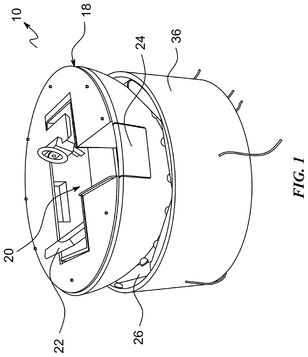
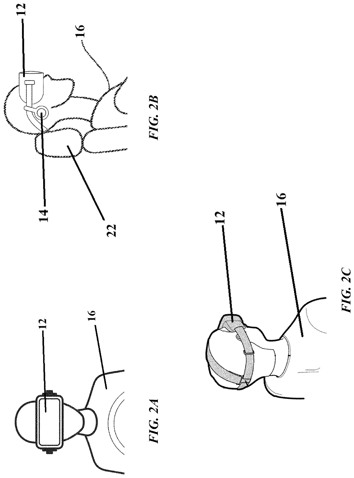
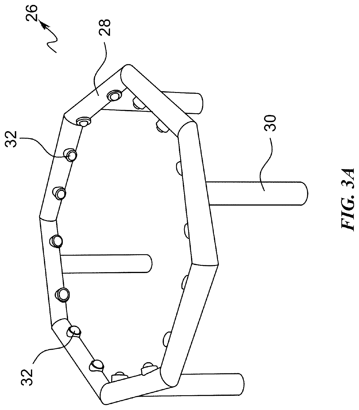
[0036]10—Immersive Multimodal Ride Simulator[0037]12—VR Headset[0038]14—Headphones[0039]16—User[0040]18—Cockpit[0041]20—Cabin[0042]22—Seat[0043]24—Door[0044]26—Cradle[0045]28—Hexagonal Frame[0046]30—Leg[0047]32—Omnidirectional Load Bearing Transfer Units[0048]34—Upright Member[0049]36—Wall[0050]38—Pitch Actuator[0051]40—Roll Actuator[0052]42—Yaw Actuator[0053]44—Extension Member[0054]46—Heave Actuator[0055]48—Piston[0056]50—Cylinder[0057]52—Retract Flow Port[0058]54—Extend Flow Port[0059]56—Ball & Socket Joint

[0060]Embodiments of the present disclosure are explained in detail below with reference to the various figures. In the following description, numerous specific details are set forth to provide an understanding of the embodiments and examples. However, those of ordinary skill in the art will recognize a number of equivalent variations of the various features provided in the description. Furthermore, the embodiments and examples may be used together in ...


PUM


Abstract

Disclosed is an immersive multimodal ride simulator comprising a virtual reality unit for delivering audio-visual simulation of a ride experience to a user, a motion unit for delivering motion simulation of the ride experience to the user wherein, the motion unit comprises a user cockpit, the exterior of which being at least partially rounded, the cockpit comprising an extension member extending therefrom, and a cradle comprising a plurality of omnidirectional load-bearing units. The cradle receives the cockpit such that, the conveyor units permit the 3D rotational movement of the cockpit. The simulator further comprises an actuation assembly for imparting rotational motion to the extension member resulting in the cockpit being subjected to three-dimensional rotation and imparting vertical motion to provide vertical movement. A controller assembly enables the user to interact simultaneously with the audio-visual simulation and motion simulation actuators without having to directly interface to the motion simulation software.

Description

CROSS-REFERENCE TO RELATED APPLICATIONS[0001]This application claims priority to U.S. Provisional Application No. 62 / 657,011 entitled “Immersive Multimodal Motion Simulator” filed Apr. 13, 2018, which is hereby incorporated by reference in its entirety.TECHNICAL FIELD[0002]The present disclosure generally relates to vehicular motion simulators and more particularly to an improved, low-cost, immersive multimodal motion simulator that eliminates simulation software interface between user controls and motion simulation.BACKGROUND[0003]Proper training is critical for mastering any skill. For example, learning to drive an automobile is a complex skill requiring a substantial amount of practice. Teenagers' lack of driving experience, together with risk-taking behavior, puts them at heightened risk for crashes. Even with current day training approaches, motor vehicle crashes are the leading cause of death for U.S. teens. The crash risk of newly licensed teens is particularly high during th...

Claims


Application Information

Patent Timeline
Patent Type & Authority Patents(United States)
IPC IPC(8): G09B9/14G09B9/30
CPCG09B9/14G09B9/302G09B9/307
Inventor PLATT, CURTIS D.
Owner PLATT CURTIS D
Why Eureka
Try Eureka