Laser measuring machine

A laser measurement and laser technology, applied in the field of laser measurement machines, can solve the problem of inability to obtain a large tilt range and so on

Inactive Publication Date: 2010-09-29
KK TOPCON
View PDF3 Cites 0 Cited by
  • Summary
  • Abstract
  • Description
  • Claims
  • Application Information

AI Technical Summary

Problems solved by technology

[0014] However, because the conventional laser measuring machine adopts a pivot structure in which the laser projector (laser projector) is supported in a hemispherical recess, although there is very little play in the structure, there is a problem that cannot be obtained. Problems with large tilt ranges
[0015] Although there is also a laser measuring machine that uses a universal joint mechanism to support the laser projector, and uses a tilting mechanism to tilt the laser projector, but it cannot be avoided that there is play in the bearing part of the universal joint mechanism. problem, so this structure is not suitable for laser measuring machines that require precise inclination angles

Method used


Image

  • Laser measuring machine
  • Laser measuring machine
  • Laser measuring machine

Examples


Embodiment

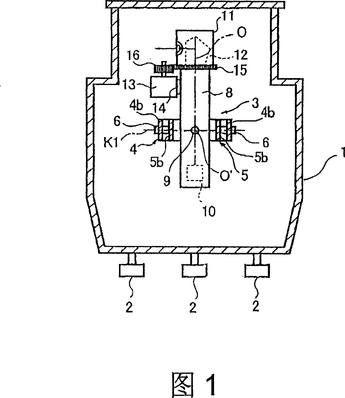
[0035] figure 1 Among them, 1 is the shell of the laser measuring machine. A calibration screw 2 is arranged on the lower part of the housing 1 . The calibration bolt 2 has the function of vertically calibrating the housing 1 .

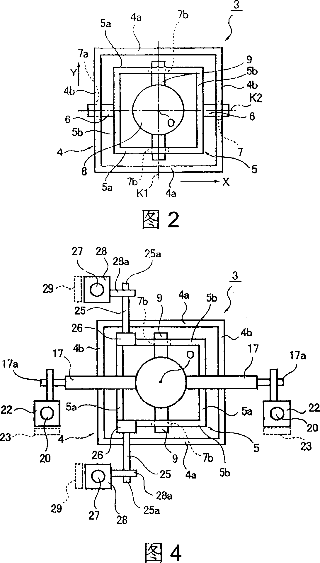
[0036] Inside this enclosure 1, as figure 2 As shown, a universal joint mechanism 3 is provided. Here, the universal joint mechanism 3 is composed of a rectangular outer frame 4 and a rectangular inner frame 5 surrounded by the outer frame 4 .

[0037] Such as figure 2 As shown, the outer frame 4 has a pair of parallel plates 4a, 4a extending along the X direction and a pair of parallel plates 4b, 4b extending along the Y direction. The outer frame 4 is fixed on the shell 1 . This inner frame 5 has a pair of parallel plates 5a, 5a extending in the X direction and a pair of parallel plates 5b, 5b extending in the Y direction.

[0038] On the pair of parallel plates 5b, 5b of the inner frame 5, a pair of shaft portions 6, 6 extending in opposi...


PUM


Abstract

The present invention relates to a surveying apparatus, even if the structure supporting the laser projector has windages, obliquity can be accurately determined. The present inventive laser surveying apparatus circulate the laser light flux from laser source 10 to form a base plane. A laser surveying apparatus includes: a laser light source configured to emit a laser light flux; a laser projector supported tiltably and configured to rotatably irradiate the laser light flux emitted from the laser light source; a mechanism tiltably supporting the laser projector; tilting arms extending in an X-direction and a Y-direction substantially perpendicular to the laser projector; a tilt driving section provided to at least one of the tilting arms configured to drive corresponding at least one of the tilting arms; detectors provided to each of the tilting arms and each configured to detect a movement amount of the corresponding one of the tilting arms, and an arithmetic section configured to calculate an inclination of the laser projector in the X-direction and the Y-direction from each of the movement amounts of the tilting arms detected by the corresponding detectors.

Description

technical field [0001] The invention relates to an improved laser measuring machine which uses a universal joint mechanism to support a tilting movable laser light projecting part. Background technique [0002] Such as Figure 8 In the shown conventional laser measuring machine, a hemispherical recess with a central opening is formed in the casing 50, and a laser projector 51 that emits laser light is engaged and supported in the recess in a tilted and movable manner. [0003] At the head of the laser projector 51, a prism holder 52 that rotates around the axis of the laser projector 51 is provided. The scanning gear is embedded in the prism holding body 52, and the prism holding body 52 is driven by the scanning motor 53' through the scanning gear to rotate around the axis. Furthermore, the prism holder 52 and the scan gear constitute a rotating portion 53 . [0004] In addition, a pentaprism 54 is provided on the prism holder 52 to deflect the laser light emitted from th...

Claims


Application Information

Patent Timeline
Patent Type & Authority Patents(China)
IPC IPC(8): G01C5/00G01C15/00
CPCG01S7/481G01S7/4813G01C15/002G01S7/4817
Inventor 古平纯一
Owner KK TOPCON
Why Eureka
Try Eureka