Apparatus for shearing multi-walled workpieces

A technology for workpieces and components, which is applied in the field of devices for cutting board materials, can solve the problems of inability to cut, not accommodate, and cannot accommodate workpieces.

Inactive Publication Date: 2000-01-19
韦恩 C 法斯克
View PDF1 Cites 3 Cited by
  • Summary
  • Abstract
  • Description
  • Claims
  • Application Information

AI Technical Summary

Problems solved by technology

[0005] A disadvantage of this existing shearing machine is that it cannot be used to conveniently cut a variety of different prefabricated pillars, gutters or similar workpieces
Each template typically forms apertures of a fixed shape and size to accommodate a manufacturer's specific type and size of workpiece and can therefore only be used for that type of workpiece
In addition, frame struts and similar workpieces are bent or slightly deformed during transport, which prevents such workpieces from being accommodated in their corresponding formwork
Thus, although such machines can be used to cut various frame posts or similar workpieces through a variety of templates having apertures of different shapes and configurations, not only is this relatively expensive, but any slightly deformed workpiece cannot be accommodated in said templates , cannot be cut by such machines

Method used


Image

  • Apparatus for shearing multi-walled workpieces
  • Apparatus for shearing multi-walled workpieces
  • Apparatus for shearing multi-walled workpieces

Examples


Embodiment Construction

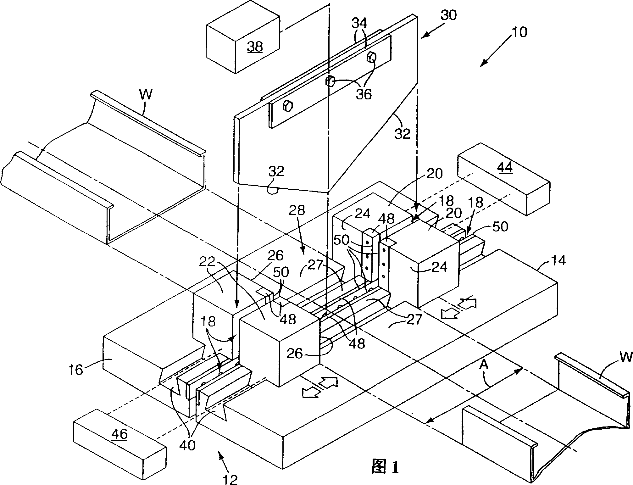
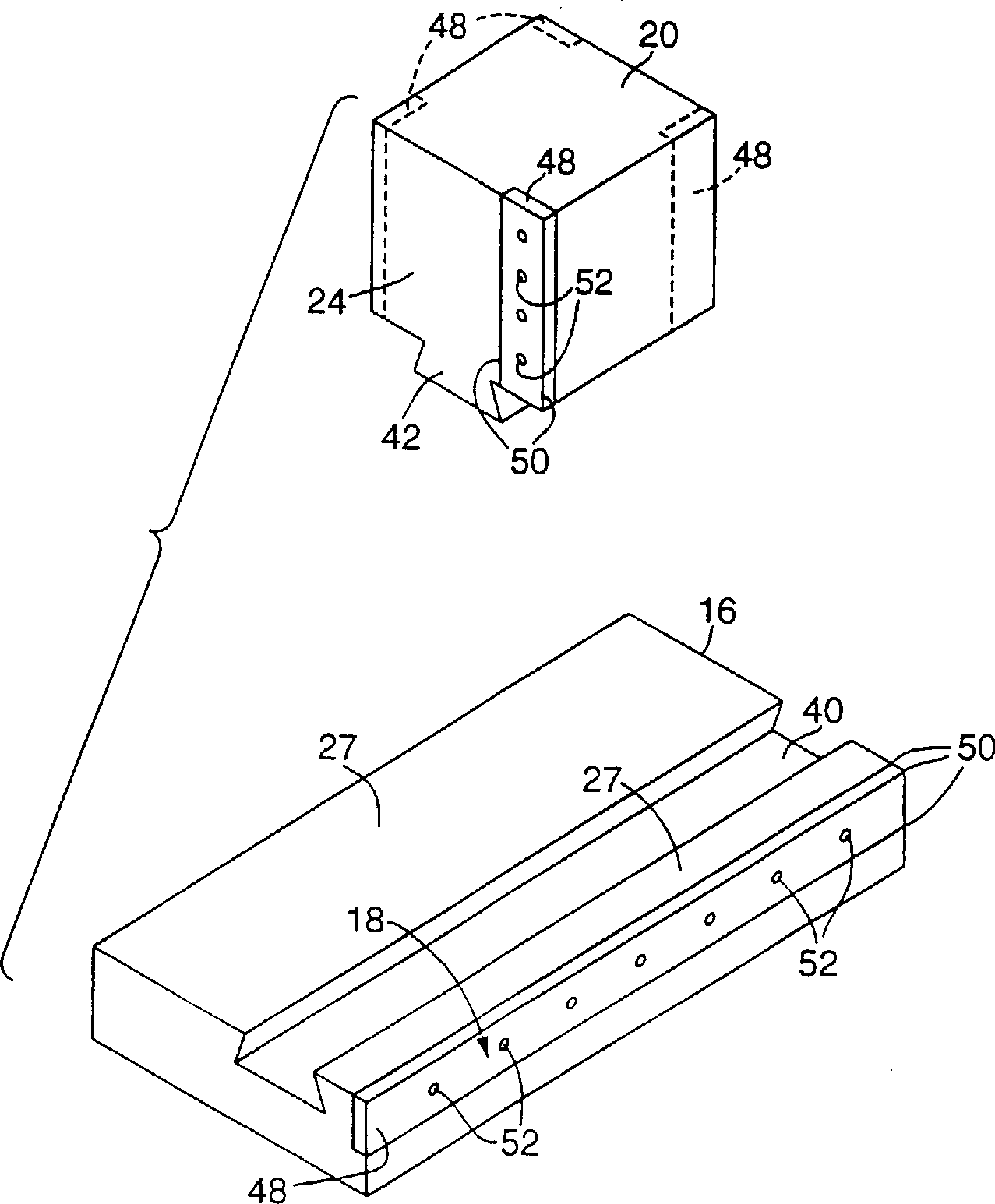
[0023] In FIG. 1, an apparatus embodying the invention is indicated by reference numeral 10 . Apparatus 10 comprises: a base assembly 12, and it contains a first base support body 14 and the second base support body 16 that is spaced apart from the first base support body, and forms blade gap 18 between them; Each of the bodies 20 is movably mounted on one side of the first and second base supports 14, 16, and each of the pair of second support bodies 22 is movably mounted on the first , On the opposite side of the second support body. Each first support 20 forms at least one first support surface 24 for engaging a first side of the workpiece 'W', and each second support 22 forms at least one second support surface 26 for engaging a second side of the workpiece W. The base supports 14, 16 similarly form a third support surface 27 extending between the first and second support surfaces 24 and 26, supporting the workpiece and cooperating with a third side thereof. In FIG. 1 , ...


PUM


Abstract

In an apparatus for shearing multi-walled workpieces, such as metal framing studs, a base support (16) defines a blade gap therebetween, and a guillotine-like blade is slidably received within the gap for shearing the workpieces. A pair of first supports (20) are each slidably mounted on a respective base support (16, 18). A pair of second supports (22) are also each slidably mounted on the base support, and are spaced apart from and face the first supports to thereby define an adjustable-width channel (28) therebetween. Each of the supports defines a blade-like edge for engaging an elongated, multi-walled workpiece and the first and second support surfaces are each moved into contact with a respective wall of the workpiece. The supports can be oriented relative to one another such that the axis of the channel, and a longitudinal axis of the workpiece received within the channel can be oriented at a desired angle relative to the blade. The guillotine-like blade is then driven downwardly into engagement with the workpiece to shear the workpiece along a line of contact.

Description

field of invention [0001] The present invention relates to apparatus for cutting sheet-like material, and more particularly, to cutting workpieces of different sizes and shapes having at least two walls of sheet-like material, such as metal frame posts and gutters. Background technique [0002] Metal framing posts are used in the construction industry, particularly in commercial construction, to construct the frame and mount siding of slate or other material thereon. While frame struts can be formed in a variety of different shapes and configurations, the common form of struts is constructed of metal and includes a rear wall and two parallel side walls forming a generally U-shaped cross-section. Commercially supplied struts are supplied in standard lengths so that if non-standard lengths are required, the standard struts must be trimmed to the required length (often by the builder). [0003] Typically on the construction site, post trimming is performed using a dicing saw w...

Claims


Application Information

Patent Timeline
Patent Type & Authority Applications(China)
IPC IPC(8): B26D7/02
Inventor 韦恩・C・法斯克
Owner 韦恩 C 法斯克
Why Eureka
Try Eureka