Portable saw table assembly

a saw table and assembly technology, applied in the field of portable saw table assembly, can solve the problems of inconvenient use of saws, inaccurate cuts in material, and flexing of saw rails, and achieve the effects of overcoming inadequacies, convenient use, and accurate cutting

Inactive Publication Date: 2009-10-29
TAPCO INTERNATIONAL CORPORATON
View PDF32 Cites 1 Cited by
  • Summary
  • Abstract
  • Description
  • Claims
  • Application Information

AI Technical Summary

Benefits of technology

[0011]The subject invention overcomes the inadequacies that characterize the related art assemblies. Specifically, the subject invention allows the material to be precisely cut at various angles. Since the saw rails do not have to extend along a diagonal, the saw rails do not flex thereby producing a more accurate cut. Also, the assembly is more convenient for use since the saw rails to extend from the table as does the related art assemblies. Further, the guide bar is moveable between predetermined angles, or pitches, to allow for quick and efficient cutting of the material. The subject invention can also be operated by a single user because it is lightweight and portable.

Problems solved by technology

The flexing of the saw rails produces inaccurate cuts in the material.
The saw rails also lose their rigidity causing the saw to rock from side to side thereby producing inaccurate cuts.
Also, the saw rails project over the edges of the table making the saw awkward to use.
However, one disadvantage of such an assembly is that the support plates must be aligned each time a different angle cut is desired.
Also, since the saw is carried by the saw rails and the saw rails must be long enough to extend along the diagonal, the saw rails may flex when cutting the material.
If the saw rails are made of a stronger material to prevent flexing, then the saw table assembly becomes heavier and makes it less portable.
Also, the saw rails project over the edges of the table making the saw awkward to use.

Method used


Image

  • Portable saw table assembly
  • Portable saw table assembly
  • Portable saw table assembly

Examples


Embodiment Construction

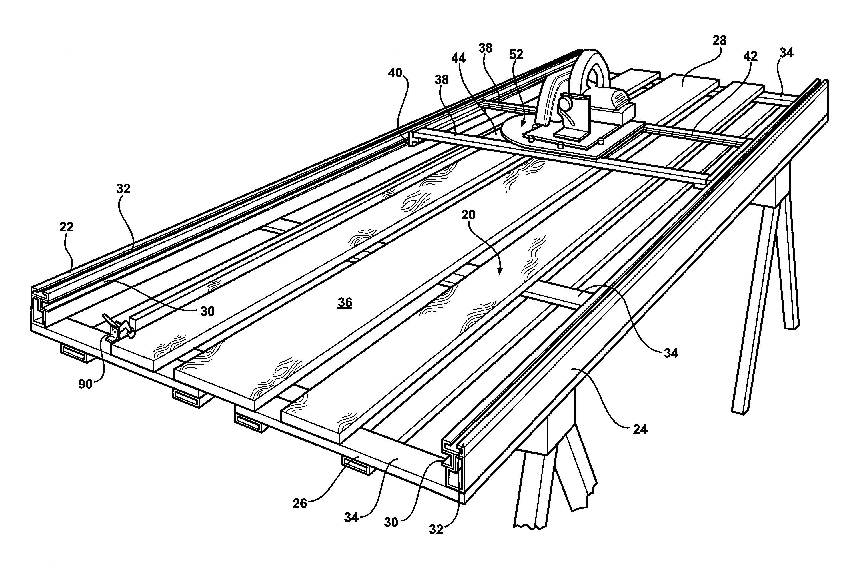
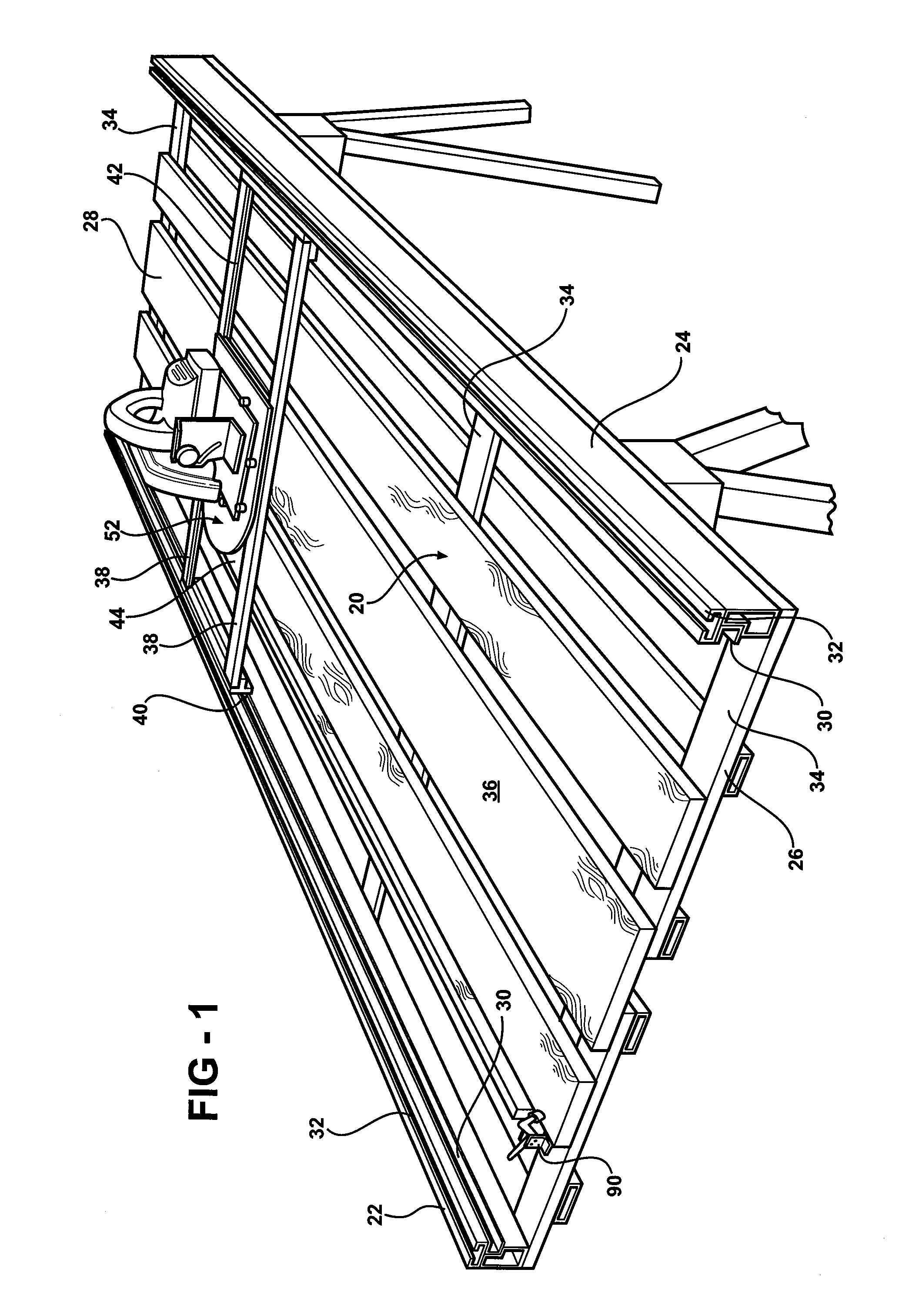
[0023]Referring to the Figures, wherein like numerals indicate like or corresponding parts throughout the several views, a portable saw table assembly for cutting a material longitudinally, laterally, and at various angles thereto is shown generally at 20 in FIG. 1. The saw table assembly 20 is particularly useful for cutting siding materials for buildings, such as vinyl siding. However, it would be equally useful for cutting other materials, such as wood. The saw table assembly 20 may be formed of any type of material capable of supporting the material to be cut, but is preferably aluminum to allow for easy transportation. Other metals may also be used so long as the assembly 20 is lightweight and portable.

[0024]The assembly 20 includes a first table rail 22 and a second table rail 24 being parallel and spaced from each other and each extending between a proximal end 26 and a distal end 28. The first and the second table rails 22, 24 are preferably C-shaped to define a channel 30 e...


PUM

PropertyMeasurementUnit
angleaaaaaaaaaa
angleaaaaaaaaaa
anglesaaaaaaaaaa

Abstract

The subject invention provides a portable saw table assembly for cutting a material longitudinally, laterally, and at various angles thereto. The assembly includes a first and a second table rail being parallel and spaced from each other and each extending between a proximal end and a distal end. A saw rail is moveably supported by the first and the second table rails for moving longitudinally along the table rails between the proximal and the distal ends and a mounting plate is moveably supported by the saw rails to allow movement of the mounting plate laterally along the saw rail between the first table rail and the second table rail. A saw plate is rotateably supported by the mounting plate for carrying a saw to cut the material. A guide bar is disposed diagonally relative to the first and the second table rails and engages the saw plate to guide the saw plate diagonally in response to simultaneous movement of the saw rail longitudinally and the mounting plate laterally.

Description

RELATED APPLICATIONS[0001]This application claims priority to U.S. provisional patent application having Ser. No. 60 / 384,298, which was filed on May 30, 2002.BACKGROUND OF THE INVENTION[0002]1. Field of the Invention[0003]The subject invention relates to a portable saw table assembly for cutting a material longitudinally, laterally, and at various angles thereto.[0004]2. Description of the Related Art[0005]Various portable saw table assemblies for cutting a material longitudinally, laterally, and at various angles thereto are known to those skilled in the art. The assemblies typically include a first table rail and a second table rail being parallel and spaced from each other and each extending between a proximal end and a distal end. A saw rail is moveably supported by the first and the second table rails for moving longitudinally along the table rails between the proximal and the distal ends and a mounting plate is moveably supported by the saw rail to move the mounting plate betw...

Claims


Application Information

Patent Timeline
Patent Type & Authority Applications(United States)
IPC IPC(8): B27B5/00B23D47/02
CPCB23D47/025B23D47/02Y10T83/7627Y10T83/8773Y10T83/7688Y10T83/7772Y10T83/8763Y10T83/7697Y10T83/8821Y10T83/95Y10T83/762Y10T83/7684Y10T83/857
Inventor LOGAN, J. RICHARDALLEN, CLYDE G.CLARK, MICHAEL C.
Owner TAPCO INTERNATIONAL CORPORATON
Why Eureka
Try Eureka