
Vibratory sensor operating as rate gyro about two axes and as rate integrating gyro about third one

A gyroscope and sensor technology, applied in the field of multi-axis sensing devices, can solve problems such as heading error

Inactive Publication Date: 2006-03-01
ATLANTIC INERTIAL SYST
View PDF3 Cites 0 Cited by
  • Summary
  • Abstract
  • Description
  • Claims
  • Application Information

AI Technical Summary

Problems solved by technology

For example, a scale factor error of 1% will result in a heading error of 3.6° per turn

Method used


Image

  • Vibratory sensor operating as rate gyro about two axes and as rate integrating gyro about third one
  • Vibratory sensor operating as rate gyro about two axes and as rate integrating gyro about third one
  • Vibratory sensor operating as rate gyro about two axes and as rate integrating gyro about third one

Examples


Embodiment Construction

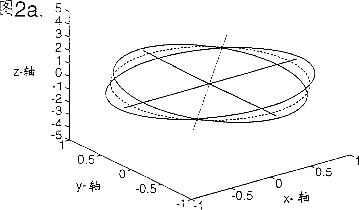
[0037] Broadly speaking, the present invention contemplates a multi-axis sensing device that operates like a rate gyroscope that rotates about two axes, x and y, and that operates like a "full angle" gyroscope about a third axis, z. . By employing the z-axis gyroscope response implemented in this mode, the carrier patterns for the x- and y-axis rate responses are no longer spatially fixed on the ring. Thus an applied rotation about the z-axis will cause the angular position of the in-plane carrier pattern to rotate about the ring.

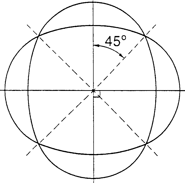
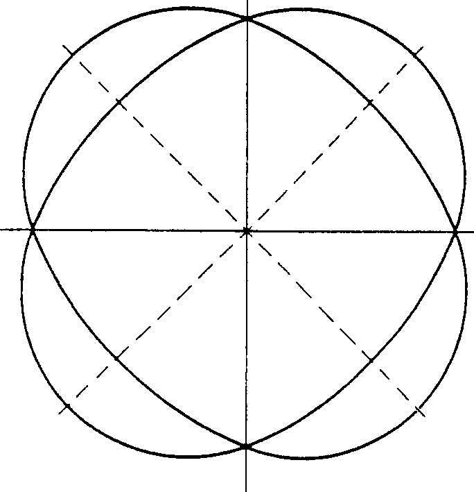
[0038] The carrier mode shape can be defined relative to a fixed angle reference direction θ = 0°, which is taken along a diameter passing through the center of the ring. The radial displacement of the ring will have a cosn(θ+α) angular distribution, where α is the angular orientation of the mode relative to the reference direction. The x and y rate response axes may also be defined relative to fixed gyroscope body reference axes, namely the y-ax...


PUM


Abstract

A vibrating structure gyroscope comprises a resonant body, a drive transducer for driving resonant motion of the body, a pick-off for producing signals representative of the resonant motion, and a signal processor for extracting z-axis orientation information and x- and y-axis rate information from the signals. The resonant body is planar and the resonant motion takes place in a vibration mode pattern whose orientation angle with respect to the body varies in accordance with z-axis orientation of the body and couples energy into an out-of-plane response mode motion in accordance with rotation of the body about the x- or y-axis. The signal processor resolves the out-of-plane response mode motion with reference to a z-axis orientation signal to extract the x- and y-axis rate information.

Description

technical field [0001] The present invention relates to multi-axis sensing devices, and more particularly to vibrating structure gyroscopes employing resonant elements. Background technique [0002] Vibrating structure gyroscopes have previously been constructed using various structures for resonating elements such as beams, tuning forks, cylinders, and rings. As disclosed in U.S. Patent No. 5,218,867, in addition to measuring rotational speed about a particular axis, these devices can also operate in a "full-angle" or "gyro" mode, where the output of the device gives A direct measurement of the angle of rotation of a shaft. It is known that this mode of operation has advantages in terms of improving the scale factor characteristics, especially in applications where the device is subjected to sustained high rotational speeds. [0003] Planar rings have proven to be particularly versatile, and single-axis rate gyroscope variants are commercially available using conventional...

Claims


Application Information

Patent Timeline
Patent Type & Authority Patents(China)
IPC IPC(8): G01C19/56G01P9/04G01C19/5677G01C19/5691
CPCG01C19/5691G01C19/5677
Inventor 克里斯托弗·P·费尔凯文·唐森德
Owner ATLANTIC INERTIAL SYST
Learn More